
Related Manuals for Ingersoll-Rand GHH RAND SILU CS85


Summary of Contents for Ingersoll-Rand GHH RAND SILU CS85
- Page 1 www.ingersollrand.com/ghhrandtransport Mounting instructions (Translation of the original instructions) SILU CS85 SILU CS1050 LITE SILU CS1050 IC...
- Page 2 WICHTIG! Die Betriebsanleitung liegt in Ihrer Landessprache zusammen mit der Montageanleitung (englische und deutsche Ausführung) elektronisch auf der Webseite www.ingersoll.com/ghhrandtransport für den Download bereit. Auf Anfrage senden wir Ihnen auch gerne eine gedruckte Version zu. IMPORTANT! The operating instructions can be downloaded electronically in your language, together with the mount‑ ing instructions (in English and German) from the website www.ingersollrand.com/ghhrandtransport.
- Page 3 IMPORTANTE! O manual de instruções está pronto para ser descarregado na sua língua-mãe, juntamente com o manual de montagem (versão em inglês e alemão), em formato eletrónico na página web www.ingersollrand.com/ghhrandtransport. A pedido, podemos também fornecer-lhe uma versão im‑ pressa. VIKTIGT! Bruksanvisningen går att hämta elektroniskt på...
- Page 4 Introduction Before installing and commissioning the SILU CS85 screw compressor or the SILU CS1050 LITE, SILU CS1050 IC compressor units, please read through these mounting instructions carefully (the additional designation SILU is not used in the rest of these mounting instructions). The mounting instructions describe how to erect and commission the above‑mentioned compressors.
-
Page 5: Table Of Contents
Contents GENERAL ............................ 7 Application ............................7 Manufacturer's address .......................7 Screw compressor type plate .......................7 Compressor unit type plate ......................8 Information for enquiries and orders ..................8 Service & Support .........................8 Technical data CS85 screw compressor ..................9 1.7.1 Performance data CS85 screw compressor ................11 Technical data CS1050 LITE compressor unit ................13 Technical data CS1050 IC compressor unit ................14 1.10... - Page 6 3.6.6 Mounting the discharge silencer ....................28 3.6.7 Installing the safety valve ......................29 3.6.8 Mounting the non-return flap....................30 3.6.9 Installing the oil dipstick ......................30 3.6.10 Installing the screw compressor on the mounting console (third‑party manufacturer) ..31 3.6.11 Installing the pressure line ......................31 Completion of the compressor unit ...................32 3.7.1 Test mounting of the compressor unit ..................32...
-
Page 7: General
General 1 General Application GHH RAND builds and supplies the CS85 screw compressor and the CS1050 compressor units for installa‑ tion on silo vehicles for the connection‑ready unit. Because of their oil‑free compression of atmospheric air and their power‑to‑weight ratio for installation on silo vehicles, the compressor unit is used to pneumatically convey bulk goods, such as flour, sugar, salt, animal feed, powdered chemicals, dry granulate, soda, cement, sand, lime, plaster, etc. -
Page 8: Compressor Unit Type Plate
General Compressor unit type plate The type plate on the compressor unit is attached to the mounting console. It contains the following information: · Type · Year of Manufacture · Compressor serial no. · Unit serial no. · V‑belt drive ratio ·... -
Page 9: Technical Data Cs85 Screw Compressor
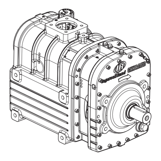
General Technical data CS85 screw compressor All dimensions are approximate Suction flange Connection for external oil cooler Pressure flange (pipeline to the oil cooler) Feather key Connection for external oil cooler Oil fill nozzle with oil dipstick (pipeline from the oil cooler) Space required to remove the oil dipstick When installing an oil cooler, replace the existing Connection for oil pressure gauge... - Page 10 General Dimensions & weight Rotational speed range Length (approx) min. rpm 1000 Width (approx.) max. rpm 2000 Height (approx) Weight (approx) Maximum operating pressure Oil filling quantity max. 2.5 bar approx. 8.5 litres Maximum intake negative pressure Minimum oil pressure max. 65 mbar min. 0.3 bar Connection dimensions Thread of attachment screw 4 x M16 Intake flange NW100/Ø140 ‑...
-
Page 11: Performance Data Cs85 Screw Compressor
General 1.7.1 Performance data CS85 screw compressor All information for: Pressure difference: Feed medium: atmospheric air Drive speed Intake pressure: 1 bar (abs.) Intake volume 1.0 bar Intake temperature: 20 °C Final temperature 1.5 bar Permitted min. ambient temp.: -20 °C Coupling output 2.0 bar Relative humidity: 60 % Permitted intake temperature 2.5 bar... - Page 12 General All information for: Pressure difference: Feed medium: atmospheric air Drive speed Intake pressure: 1 bar (abs.) Intake volume 1.0 bar Intake temperature: 20 °C Final temperature 1.5 bar Permitted min. ambient temp.: -25 °C Coupling output 2.0 bar Relative humidity: 60 % Permitted intake temperature 2.5 bar 1,max Technical data without intake or pressure losses...
-
Page 13: Technical Data Cs1050 Lite Compressor Unit
General Technical data CS1050 LITE compressor unit Model: R - PTO L (standard ratio) All dimensions are approximate. Model: L - PTO R (standard ratio) All dimensions are approximate. 47757783 A... -
Page 14: Technical Data Cs1050 Ic Compressor Unit
General Technical data CS1050 IC compressor unit Model: R - PTO L (standard ratio) All dimensions are approximate. Model: L - PTO R (standard ratio) All dimensions are approximate. 47757783 A... -
Page 15: Technical Data Compressor Unit
General 1.10 Technical data compressor unit Dimensions & weight CS1050 CS1050 CS1050 CS1050 LITE R-PTO L LITE L-PTO R IC R-PTO L IC L-PTO R Width (approx.) Depth (approx.) Height (approx) Weight (approx) Speed range at Unit CS1050 units standard ratio* Compressor unit drive speed 1200 1600 V‑belt drive transmission ratio (standard) 1.25... -
Page 16: Operating The Compressor At High Altitudes
General 1.11 Operating the compressor at high altitudes If operating the compressor at high altitudes, make sure that, depending on the existing ambient pres‑ sure, the operating overpressure must be reduced in order to prevent temperature damage to the com‑ pressor and compressor unit. -
Page 17: External Oil Cooler For Extreme Conditions
General 1.13 External oil cooler for extreme conditions To give the compressor an optimum service life, an external oil cooler* must be operated under the following conditions: a) When operating in an enclosed environment (encapsulated), e.g. customer‑owned direct‑driven or belt‑driven systems with a cover/casing, or our own electrical / diesel systems, b) When operating in challenging/cramped environments, e.g. -
Page 18: Safety
Safety 2 Safety General These mounting instructions contain fundamental instructions which must be adhered to when per‑ forming assembly and installation. This mounting instruction must therefore be read in full by the responsible specialist staff before starting work. Authorised personnel, training and qualification Installation and assembly work must only be carried out by persons with the appropriate authorisation, training and qualifications, who are familiar with the valid safety regulations. -
Page 19: Unauthorised Conversions And Spare Parts
Safety Unauthorised conversions and spare parts Conversions and modifications to the screw compressor and screw compressor unit are not permitted. In the event of damage to the lead seal, any warranty claims are invalid. Original replacement parts and accessories that are authorised by the manufacturer represent safety factors. -
Page 20: Installation Guidelines
Installation guidelines 3 Installation guidelines NOTE Also observe the safety instructions in Chapter 2 on page 18. Internal transportation 3.1.1 Internal transportation of the screw compressor The screw compressor and the accessories are delivered separately. The screw compressor is on a pallet and secured with straps. The accessories are delivered in a separate box. -
Page 21: Internal Transportation Of The Unit
Installation guidelines 3.1.2 Internal transportation of the unit The compressor unit (1) is fastened to a euro‑pallet (2). For transportation, use a sufficiently dimen‑ sioned lifting truck/fork lift. WARNING RISK OF TIPPING OVER IF TRANSPORTED ON THE GROUND! If using internal transport with insufficiently dimensioned transportation equipment, there is a risk of tipping over and injuries. -
Page 22: Articulated Shaft
Installation guidelines 3.2.2 Articulated shaft The V-belt drive is usually carried out through an articulated shaft between the power take-off of the vehicle drive and bearing block (bearing of the belt pulley). Selection of articulated shaft Consider the following items during the determination of the articulated shaft: ‣... -
Page 23: Permitted Inclination
Installation guidelines 3.3.1 Permitted inclination NOTICE INSUFFICIENT LUBRICATION! Excessive inclination results in irregular level of lubricant in the housing. ‣ Observe the maximum permitted inclination of the screw compressor during operation: · To the front and to the rear: 10° · To the right and left: 10° Preparing installation The approximate position of the compressor and the compressor unit on the vehicle must be deter‑... -
Page 24: Air Flow Cs1050 Ic
Installation guidelines NOTICE DAMAGE TO THE BEARING! Non-observance of attachment, flange parallelism and angle of inclination of the articulated shaft can result in significant bearing loads, with the result of premature damage to the bearing. ‣ Fundamentally, the structural guidelines from the manufacturer of the respective vehicle and tech‑ nical information provided by the manufacturer of the articulated shaft with regard to attachment, flange parallelism and angle of inclination of the articulated shaft must be adhered to. -
Page 25: Completion Of The Screw Compressor
Installation guidelines Completion of the screw compressor NOTICE FOREIGN OBJECTS IN THE COMPRESSOR! If foreign objects enter the screw compressor during completion, the screw compressor will be destroyed when it is started up. ‣ Make sure that no foreign objects enter the screw compressor. 3.6.1 Installing the hose connection flange (example) NOTE... -
Page 26: Installing The Oil Pressure Gauge
Installation guidelines 3.6.3 Installing the oil pressure gauge NOTICE HIGH OPERATING TEMPERATURES! The oil pressure gauge can be damaged if it is exposed to ambient temperatures greater than 60 °C. ‣ Do not install the oil pressure gauge close to hot parts or in the exhaust area of the safety valve. ‣... -
Page 27: Installing The Intake Silencer And Air Filter
Installation guidelines 3.6.5 Installing the intake silencer and air filter The air filter and combined intake silencer (with integrated air filters) for the compressor available from GHH RAND must be suitably dimensioned with regard to the noise emission and filter capacity of the application on the silo vehicle. -
Page 28: Mounting The Discharge Silencer
Installation guidelines 3.6.6 Mounting the discharge silencer CAUTION NOISE GENERATION! Excessive noise exposure can lead to health problems. ‣ A discharge silencer is used to reduce the noise level. Further measures for reducing the noise level on the system side are recommended. ‣... -
Page 29: Installing The Safety Valve
Installation guidelines 3.6.7 Installing the safety valve NOTE When installing a safety valve, observe the manufacturer instructions. The safety valve (overpressure valve) is used as a safety mechanism for the compressor. In order to prevent the operating pressure from increasing to impermissible levels, it should be of an encapsulated design. -
Page 30: Mounting The Non-Return Flap
Installation guidelines The safety valve from GHH RAND must only be installed as illustrated (0° ... 90°): NOTICE INCORRECT INSTALLATION POSITION OF THE SAFETY VALVE! An incorrect installation position of the safety valve can result in destruction of the compressor. ‣ The safety valve must only be installed at an angle of 0°... -
Page 31: Installing The Screw Compressor On The Mounting Console (Third-Party Manufacturer)
Installation guidelines 3.6.10 Installing the screw compressor on the mounting console (third-party manufac- turer) ‣ Install the screw compressor on the mounting console taking the installation position into account (Chapter 3.3 on page 22). At least four fastening screws (min. screw size: M16 10.9, hexagon screw with shaft) must be used. ‣... -
Page 32: Completion Of The Compressor Unit
Installation guidelines Completion of the compressor unit 3.7.1 Test mounting of the compressor unit To determine the exact installation position on the vehicle frame and the fastening bores in the adapt‑ er, it is necessary to position the compressor unit with adapter on the vehicle frame with the assembly console. - Page 33 Installation guidelines NOTICE SUFFICIENT DIMENSIONING OF THE DRILL HOLES! Fit the mounting console with at least ten drill holes Ø 14.5 mm (min. screw size: hexagon screw with shaft M14 10.9 with the corresponding washer and self-locking nut). ‣ Preferably use the screw connections recommended by the vehicle manufacturer for load-bearing frame mounts.
-
Page 34: Installing The Compressor Unit
Installation guidelines 3.7.2 Installing the compressor unit ‣ Position the adapter on the vehicle frame as deter‑ mined in the test mounting (Chapter 3.7.1 on page 32). ‣ Screw the adapter (1) to the vehicle frame (2) using screws (3). Tightening torque (M14 10.9): 193 Nm ‣... -
Page 35: Installing The Articulated Shaft
Installation guidelines ‣ Separate the compressor unit from the pallet (1) by unfastening the four screw connections (2). CAUTION RISK OF CRUSHING! There is a risk of crushing if the compressor unit falls down. ‣ Support the pallet with the lift truck or forklift until the four screw connections have been un‑... - Page 36 Installation guidelines NOTICE DAMAGE TO THE COMPRESSOR! Incorrect selection of the V‑belt can cause damage to the compressor. ‣ Use the correct V‑belt length and V‑belt type. Contact GHH RAND if necessary. ‣ Check the alignment of the V‑belt pulley. NOTE For an optimal service life of the V‑belt drive, the alignment of the V‑belt pulleys must be checked after moving the bearing block.
-
Page 37: Connecting The External Oil Cooler (Optional)
Installation guidelines Connecting the external oil cooler (optional) NOTE If the GHH RAND screw compressor or the compressor unit be operated under the conditions listed in Chapter 1.13 on page 17, a suitably selected oil cooler must be installed. The oil cooler supply and return must be connected in accordance with the data given in Chapter 1.7 on page 9 and Chapter 3.6.4 on page 26 . -
Page 38: Connecting The Control Unit Cs1050 Ic
Installation guidelines Connecting the control unit CS1050 IC ‣ Attach the control unit for supplying power for the cooling fan to the connection option for 24 V DC provided by the vehicle manufacturer. The connection must be fused with at least 20 A. The IC unit can either be connected to continuous or ignition voltage. -
Page 39: Safety Labels
Safety labels 4 Safety labels The safety labels must by attached by the installer of the system. Apply maintenance instructions and lubricant recommendation (use the version in the local language of the operator)! ‣ Affix safety labels, maintenance instruction and lubricant recommendation to the relevant points of the installed compressor. -
Page 40: Attaching The Stickers To The Unit (Example)
Safety labels Attaching the stickers to the unit (example) 47757783 A... -
Page 41: Initial Commissioning
Initial commissioning 5 Initial commissioning Initial commissioning is carried out by the installer of the system. It includes filling with lubricant, removing the preservation, the test run with a check of the direction of rotation and speed, as well as the function control of the fan (IC unit). If in exceptional cases the first start of operation is carried out by the customer, the following work has to be carried out: Work... -
Page 42: Filling With Lubricant
Initial commissioning Filling with lubricant NOTICE DAMAGE DUE TO INCORRECT OILS! Incorrect oils can destroy the compressor. ‣ Only use specified oil. ‣ Unscrew the oil dipstick (1). ‣ Top up with new oil according to the lubricant recommendation (Chapter 5.1 on page 41): CS85/CS1050: approx. -
Page 43: Test Run
Initial commissioning Test run CAUTION HOT SURFACES! During operation, the compressor and discharge silencer are very hot. There is a risk of burning. ‣ Wear protective gloves. CAUTION NOISE GENERATION! An excessive acoustic pressure level can result in damage to hearing. ‣ Do not operate the compressor without the discharge silencer. ‣... -
Page 44: Checking The Drive Speed
Initial commissioning 5.4.3 Checking the drive speed NOTICE INCORRECT SPEED RANGE! An incorrect speed range can destroy the compressor. ‣ Ensure that the compressor is only operated within its permissible rotational speed range. ‣ Check the drive speed of the screw compressor. The speed must remain within the speed range for the screw compressor specified in the technical data. -
Page 45: Checks After The Test Run
Initial commissioning NOTE The non‑return valve installed in the compressor unit prevents the compressor from running back‑ wards rapidly and for a long time (as a result of residual pressure in the compressed air lines of the pneumatic system) after being switched off. In order to avoid an undesired blowback of material into the compressor, it is compulsory that at least one additional non-return flap be provided in the pneumatic system of the silo construction. - Page 46 Service & Support www.ingersollrand.com/ghhrandtransport Subject to revision without notice Printed in Fed. Rep. of Germany 12/2022 EN...
Need help?
Do you have a question about the GHH RAND SILU CS85 and is the answer not in the manual?
Questions and answers