
Related Manuals for Ingersoll-Rand GHH RAND SILU CS1050 LITE


Summary of Contents for Ingersoll-Rand GHH RAND SILU CS1050 LITE
- Page 1 www.ingersollrand.com/ghhrandtransport Operating manual (Translation of the original instructions) SILU CS85 SILU CS1050 LITE SILU CS1050 IC...
- Page 2 WICHTIG! Die Betriebsanleitung liegt in Ihrer Landessprache zusammen mit der Montageanleitung (englische und deutsche Ausführung) elektronisch auf der Webseite www.ingersoll.com/ghhrandtransport für den Download bereit. Auf Anfrage senden wir Ihnen auch gerne eine gedruckte Version zu. IMPORTANT! The operating instructions can be downloaded electronically in your language, together with the mount‑ ing instructions (in English and German) from the website www.ingersollrand.com/ghhrandtransport.
- Page 3 IMPORTANTE! O manual de instruções está pronto para ser descarregado na sua língua-mãe, juntamente com o manual de montagem (versão em inglês e alemão), em formato eletrónico na página web www.ingersollrand.com/ghhrandtransport. A pedido, podemos também fornecer-lhe uma versão im‑ pressa. VIKTIGT! Bruksanvisningen går att hämta elektroniskt på...
- Page 4 Introduction Before installing and commissioning the SILU CS85 screw compressor or the SILU CS1050 LITE, SILU CS1050 IC compressor units, please read through these operating instructions carefully (the addi‑ tional designation SILU is not used in the rest of these operating instructions). The operating manual contains important instructions which must be strictly followed if trouble‑free operation and a long service life are to be ensured.
-
Page 5: Table Of Contents
Contents GENERAL ............................ 7 Application ............................7 Manufacturer's address .......................7 Identification ..........................7 Information for enquiries and orders ..................7 Service & Support .........................7 Technical data CS85 screw compressor ..................8 Technical data CS1050 compressor units ..................9 Operating the compressor at high altitudes ................10 Lubricant .............................10 1.10 Screw compressor type plate .....................11... - Page 6 FAULTS, CAUSE AND INSTRUCTIONS FOR TROUBLESHOOTING ..........31 47757782 A...
-
Page 7: General
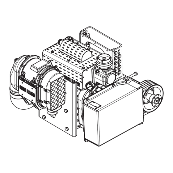
General 1 General Application GHH RAND builds and supplies the CS85 screw compressor and the CS1050 screw compressor unit. Because of their oil‑free compression of atmospheric air and their power‑to‑weight ratio for installation on silo vehicles, the compressor unit is used to pneumatically convey bulk goods, such as flour, sugar, salt, animal feed, powdered chemicals, dry granulate, soda, cement, sand, lime, plaster, etc. -
Page 8: Technical Data Cs85 Screw Compressor
General Technical data CS85 screw compressor Dimensions & weight Rotational speed range Length (approx.) min. rpm 1000 Width (approx.) max. rpm 2000 Height (approx.) Weight (approx.) Maximum operating pressure Oil filling quantity max. 2.5 bar approx. 8.5 litres Maximum intake negative pressure Minimum oil pressure max. 65 mbar min. 0.3 bar Performance data Unit CS85 Rotary valve compressor 1000 1500 2000... -
Page 9: Technical Data Cs1050 Compressor Units
General Technical data CS1050 compressor units Dimensions & weight CS1050 CS1050 CS1050 CS1050 LITE R-PTO L LITE L-PTO R IC R-PTO L IC L-PTO R Width (approx.) Depth (approx.) Height (approx.) Weight (approx.) Speed range at standard ratio* Unit CS1050 units Compressor unit drive speed 1200 1600 V‑belt drive transmission ratio (standard) 1.25 CS85 compressor rotational speed... -
Page 10: Operating The Compressor At High Altitudes
General Operating the compressor at high altitudes If operating the compressor at high altitudes, make sure that, depending on the existing ambient pres‑ sure, the operating overpressure must be reduced in order to prevent temperature damage to the com‑ pressor. This should be carried out in accordance with the following table: Installation height h [m] 1000... -
Page 11: Screw Compressor Type Plate
General 1.10 Screw compressor type plate The type plate is attached to the side of the screw compressor. It contains the following information: · Type · Serial number · Rotational speed range · Max. volume flow · At max. operating pressure ·... -
Page 12: Safety
Safety 2 Safety General This operating manual contains basic instructions to be followed during operation and maintenance/ repair. Therefore, this operating manual must be read by the responsible technical staff/operator prior to commissioning and it must always be available at the place of use for the screw compressor. Authorised personnel, training and qualification Work carried out on the compressor, such as operation and maintenance/repair, must only be carried out by persons with the appropriate authorisation, training and qualifications, who are familiar with the... -
Page 13: Unauthorised Conversions And Spare Parts
Safety Unauthorised conversions and spare parts Conversions and modifications to the screw compressor and screw compressor unit are not permitted. Damage to the seal will void any warranty claims. Original replacement parts and accessories that are authorised by the manufacturer represent safety factors. The use of non‑original or unauthorised re‑ placement and accessory parts may void the liability for resulting consequences. -
Page 14: Operation
Operation 3 Operation Safety during operation NOTE Also observe the safety instructions in Chapter 2 on page 12. DANGER RISK OF EXPLOSION! For the conveyance of combustible, dust‑like materials, the temperature of the compressed air at the measurement point directly before contact with the material to be conveyed may not exceed the maxi‑ mum value of 120 °C. -
Page 15: Installation
Operation Installation ‣ Park the vehicle in as level a position as possible. ‣ Observe the permitted inclination. Permitted inclination NOTICE INSUFFICIENT LUBRICATION! Excessive inclination results in irregular level of lubricant in the housing. ‣ Observe the maximum permitted inclination of the screw compressor during operation: ·... -
Page 16: Monitoring Operation
Operation Monitoring operation 3.5.1 CS85/external installation The manufacturer installs a gauge (measurement position in the following pipeline) pneumatic system to monitor the compression pressure. The system manufacturer or external installer must also install displays that monitor the intake negative pressure and the oil pressure of the compressor stage. For the operation and control of the operating displays, only the instructions from the manufacturer are applica‑... - Page 17 Operation Maintenance indicator variant 1 The negative pressure in the compressor is displayed on the maintenance indicator (1). The negative pressure must not exceed 65 mbar (red area on the maintenance indicator). NOTICE PERMITTED NEGATIVE PRESSURE EXCEEDED! Excessive negative pressure (> 65 mbar) can result in overheating and damage to the compressor.
-
Page 18: Cs1050 Ic
Operation 3.5.3 CS1050 IC Cooling fan speed selector switch Operation and fault monitoring Compressed air temperature indicator Negative pressure maintenance indicator Oil pressure display Once the compressor unit has started and the min. oil pressure has been reached, the control unit switches on automatically. -
Page 19: External Oil Cooler For Compressor (Optional)
Operation Resetting the maintenance indicator If the negative pressure has dropped to below the permitted limit (65 mbar, red area on the maintenance indicator), the maintenance indicator must be reset after rectification of the malfunction. ‣ Push the button (2) on the front of the maintenance indicator (1). Operation and fault monitoring The operating display lights up green continuously when the compressor is operating. -
Page 20: Switching Off
Operation Switching off NOTICE RISK OF BLOWBACK OF MATERIAL! If the compressor is switched off if there is counter pressure, there is the risk of damage to the non- return flap due to blowback of material. ‣ Do not turn compressor off if there is counter pressure! ‣... -
Page 21: Maintenance/Repair
Maintenance/repair 4 Maintenance/repair Safety NOTE Also observe the safety instructions in Chapter 2 on page 12. WARNING COMPRESSED AIR IN THE SYSTEM! There is a risk of injury due to pressurized components and lines. ‣ All checks and maintenance tasks must only be performed with the compressor switched off and depressurised. -
Page 22: Maintenance Intervals
Maintenance/repair Maintenance Intervals All of the maintenance and repair tasks given on this page are described in detail in the following Chap- ter 4.4 on page 23. After the first 2 operating hours Section 4.4.1 Readjust the tension of the V‑belts and quick‑release bushings of the V‑belt pulleys. 4.4.2 Re‑tighten the fastening screws on the discharge silencer. -
Page 23: Maintenance Work
Maintenance/repair Maintenance work 4.4.1 Readjusting the tension of the V-belts and quick-release bushings of the V-belt pulleys NOTE For the maintenance of the belt drive of a compressor unit based on the CS85 compressor stage (third‑party manufacturer), only the instructions from the manufacturer are applicable. The following applies to the CS1050 unit: NOTICE ELONGATED V-BELT! - Page 24 Maintenance/repair Adjusting the tension of the quick-release bushings of the V-belt pulleys ‣ Retighten the V‑belt pulley screws (1 and 2). Quick-release bushing tightening torques Belt pulley nomi- Quick- Tightening nal diameter release torque bushings 180 mm 200 mm 3020 90 Nm 224 mm 250 mm 280 mm 3525 112 Nm 315 mm Checking and setting the tension of the...
-
Page 25: Retightening The Fastening Screws On The Discharge Silencer
Maintenance/repair 4.4.2 Retightening the fastening screws on the discharge silencer CS1050 LITE Remove the upper unit covering in order to access the discharge silencer screws. ‣ Unscrew the screws (1) from the upper cover (2). ‣ Lift the cover off. ‣... -
Page 26: Checking The Oil Level
Maintenance/repair ‣ Tighten the fastening screws (2) on the discharge silencer (1), tightening one screw then tightening the screw opposite. Tightening torque (M12 A2-70): 65 Nm ‣ Reinstall the cover. Tightening torque (M6 A2-70): 7 Nm 4.4.3 Checking the oil level ‣ Unscrew the oil dipstick (1) (unit). ‣ Unscrew the oil dipstick (2) (CS85). ‣... -
Page 27: Cleaning And Replacing The Intake Filter Element
Maintenance/repair 4.4.4 Cleaning and replacing the intake filter element For the maintenance or replacement of the intake filter of a compressor unit based on the CS85 com‑ pressor stage (third‑party manufacturer), only the instructions from the manufacturer are applicable. NOTE Intake filters from diverse manufacturers can be installed. -
Page 28: Check The Safety Valve
Maintenance/repair 4.4.5 Check the safety valve The safety valve is usually installed on the discharge silencer. NOTE The discharge silencers (1) supplied by GHH RAND have an integrated safety valve (2). ‣ In order to check the knurled nut (1), release the safety valve (2). -
Page 29: Check The Non-Return Flap
Maintenance/repair 4.4.6 Check the non-return flap For the maintenance or replacement of the non-return flap of a compressor unit based on the CS85 com‑ pressor stage (third‑party manufacturer), only the instructions from the manufacturer are applicable. NOTE Non-return flaps from diverse manufacturers can be installed. Also observe the instructions from the manufacturer. -
Page 30: Oil Change And Cleaning The Oil Intake Strainer
Maintenance/repair 4.4.8 Oil change and cleaning the oil intake strainer CAUTION ENVIRONMENTAL POLLUTION THROUGH OIL! Very small quantities of oil are sufficient to make significant amounts of potable water unusable. ‣ During the oil change, make sure that no oil is released into the environment. ‣... - Page 31 Faults, cause and instructions for troubleshooting 5 Faults, cause and instructions for troubleshooting If in doubt, switch off the compressor! Fault Possible cause Remedy Section 1.6 - 1.8 Air quantity not sufficient Drive speed too low Increase drive speed to the maxi‑ mum permitted speed Suction filter soiled/clogged Clean or replace filter cartridges or 4.4.4 elements as necessary...
- Page 32 Faults, cause and instructions for troubleshooting Fault Possible cause Remedy Section 4.4.8 Oil foams Wrong type of oil Drain oil completely and top up with specified oil Water in the oil Oil quality different 4.4.3 & Oil level too high Check oil level and drain off oil as necessary 4.4.8 4.4.3 &...
- Page 33 Faults, cause and instructions for troubleshooting Printed in Germany Reserves the right to amend technical details compared to the information and illustrations of the oper‑ ating manual. A replication, copying or translation, even in parts, is not permitted without written con‑ sent. As a contribution to environmental protection: This paper has been produced from 100% chlorine free bleached pulp.
- Page 34 Service & Support www.ingersollrand.com/ghhrandtransport Subject to revision without notice Printed in Fed. Rep. of Germany 12/2022 EN...
Need help?
Do you have a question about the GHH RAND SILU CS1050 LITE and is the answer not in the manual?
Questions and answers