Advertisement
Quick Links
Quick Installation Guide
Version 1.1
Export Power Manager
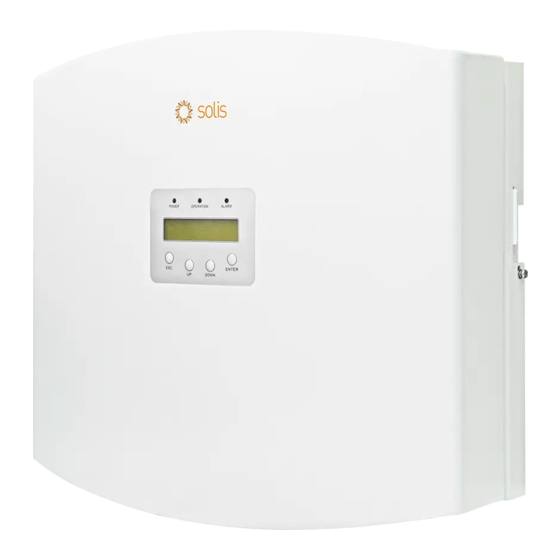
EPM3-5G-PLUS
Note:
Quick installation is for reference only.
Read the instructions carefully before installing and using
the product.
For access to the manual please scan
the QR code below or you can go the URL
https://www.ginlong.com/global/
service.html
After entering the page, you can click "
k "
icon to change to preferred language.
1
Determine location of EPM
Following minimum clearance is required.
300mm
300mm
300mm
Install the EPM
2
Step 1: Mark A,B,C,D mounting holes on the wall.
A
C
Step 2: Drill four φ8 holes and fix the bracket onto the wall with
expansion bolts.
"
"
Manual Download
Step 3: Hang the EPM on the bracket by the steps below.
300mm
Step 4: Fix the two locking screw on both side of the bracket
and connect the grounding wire to the grounding screw.
M4 locking screw
B
D
M4 locking screw
Grounding screw
Advertisement

Subscribe to Our Youtube Channel
Summary of Contents for SOLIS EPM3-5G-PLUS
- Page 1 Step 3: Hang the EPM on the bracket by the steps below. Following minimum clearance is required. Version 1.1 Export Power Manager 300mm EPM3-5G-PLUS 300mm 300mm Step 4: Fix the two locking screw on both side of the bracket and connect the grounding wire to the grounding screw.
- Page 2 Connect cables LCD Setting of EPM 3.1 Grid input cable -> Grid Port 3.3 CT cables -> CT1/CT2/CT3 Ports After EPM is powered on, LCD needs to do the following settings. Connect the grid input cables to the grid connector and then Connect the CT connectors to the EPM CT ports, and make sure Setting Path 1: Settings(For 4.1) to the Grid port of the EPM as described below.
- Page 3 4.4.2 Set Meter CT 4.6 Select Export Work Mode 4.11 Set CT Check Set the CT(Current Transformer) ratio according to the actual CT Average Mode: Each phase of inverter will generate the power The default ”CT Check Choose” is ON, the EPM will give an alarm used at site.
- Page 4 System Diagram Contact us Ginlong Technologies Co., Ltd. No. 57 Jintong Road, Binhai Industrial Park, Xiangshan, Ningbo, Zhejiang, 315712, P.R.China. Tel: +86 (0)574 6578 1806 Fax: +86 (0)574 6578 1606 Email: info@ginlong.com Web: www.solisinverters.com...


Need help?
Do you have a question about the EPM3-5G-PLUS and is the answer not in the manual?
Questions and answers