SOLIS S6 Series User Manual
Hybrid inverter, applicable system, single phase system
Hide thumbs
Also See for S6 Series:
- User manual ,
- Manual (50 pages) ,
- Installation and operation manual (29 pages)
Table of Contents

Related Manuals for SOLIS S6 Series


Summary of Contents for SOLIS S6 Series
- Page 1 User Manual for S6 Series Hybrid Inverter Applicable models S6-EH1P3K-L-PLUS S6-EH1P3.6K-L-PLUS S6-EH1P4.6K-L-PLUS S6-EH1P5K-L-PLUS S6-EH1P6K-L-PLUS S6-EH1P8K-L-PLUS Applicable System Single phase system Version 1.0, Release Date: 08,2024...
-
Page 2: Important Notes
Every attempt has been made to make this document complete, accurate and up-to-date. Individuals reviewing this document and installers or service personnel are cautioned, however, that Solis reserves the right to make changes without notice and shall not be responsible for any damages, including indirect, incidental or consequential damages... -
Page 3: Table Of Contents
Contents 1. Introduction 01-04 ……………………………………………………………………………………………………………………………… 1.1 Product Overview ……………………………………………………………………………………………………………… 1.2 Inverter Wire Box and Connection Points ………………………………………………………………… 1.3 Product Features ………………………………………………………………………………………………………………… 1.4 Packaging ……………………………………………………………………………………………………………………………… 1.5 Tools Required for Installation ……………………………………………………………………………………… 2. Safety & Warning 05-07 …………………………………………………………………………………………………………… 2.1 Safety ……………………………………………………………………………………………………………………………………… 2.2 General Safety Instructions ……………………………………………………………………………………………... -
Page 4: Introduction
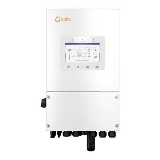
User Manual 1.1 Product Overview The Solis S6-EH1P(3-8)K-L-PLUS series is designed for residential hybrid systems. The inverter can work with low-voltage lithium ion and Lead-acid batteries to maximize self-consumption and provide backup power if the grid fails and there is not enough PV power to cover load demand. -
Page 5: Inverter Wire Box And Connection Points
7. Grid Conduit for PV conductors should be connected here 8. PV Module Input Conduit for Battery conductors should be connected here 9. Battery Connection 10. COM Port Solis data logger gets connected here-only USB version of the loggers will work... -
Page 6: Product Features
1. Introduction User Manual 1.3 Product Features Highly Flexible Integrated 2 MPPTs with 2(3-6K)/4(8K) strings, suitable for residential rooftop installations with multiple array orientations. Compatible with multiple brands of battery models giving customers multiple battery options. 7-Inch color LCD screen and built in Bluetooth provide local operation without Internet. Outstanding Performance Up to 16A(3-6K)/32A (8K)of MPPT current input to support 182mm solar panels. -
Page 7: Packaging
WiFi/GPRS Stick x1 Quick Installation Manual x1 Cable x1 RJ45 connector x4 If anything is missing, please contact your local Solis distributor. 1.5 Tools Required for Installation Torqx T20 Screwdriver Wire Strippers 12AWG to 6AWG Wire Strippers 20AWG to 10AWG... -
Page 8: Safety And Warning
2. Safety & Warning User Manual 2.1 Safety The following types of safety instructions and general information appear in this document as described below: DANGER “Danger” indicates a hazardous situation which if not avoided, will result in death or serious injury. WARNING “Warning”... - Page 9 NEC Article 690, Part II. All Solis single phase inverters feature an integrated DC disconnect switch. CAUTION Risk of electric shock, do not remove the cover. There are no serviceable parts inside, refer servicing to qualified and accredited service technicians.
-
Page 10: Notice For Use
2. Safety & Warning User Manual 2.3 Notice for Use The inverter has been constructed according to he applicable safety and technical guidelines, use the inverter in installations that meet the following specifications only: 1. Permanent installation is required. 2. The electrical installation must be compliant with all local and national regulations & standards. -
Page 11: Installation
3. Installation User Manual 3.1 Select a Location to Install the Inverter When selecting a location for the inverter, the following criteria should be considered: Exposure to direct sunlight may cause output power derating due to overheating It is recommended to avoid installing the inverter in direct sunlight. The ideal location is one where the ambient temperature does not exceed 40°C. - Page 12 Consult the technical specifications sections at the end of this manual for additional environmental condition requirements (temperature range, altitude, etc.) 3.1.3 Angle of installation This model of Solis inverter must be mounted vertically (90 degrees or backwards less than or equal to 15 degrees from 90 degrees straight up).
-
Page 13: Product Handling
3. Installation User Manual 3.1.4 Avoiding direct sunlight Installation of the inverter in a location exposed to direct sunlight should to be avoided. Direct exposure to sunlight could cause: Power output limitation (with a resulting decreased energy production by the system). Premature wear of the electrical/electromechanical components. -
Page 14: Mounting The Inverter
3. Installation User Manual 3.3 Mounting the Inverter Mount the inverter on a wall or structure capable of bearing the weight of the machine. The inverter must be mounted vertically with a maximum incline of +/- 5 degree. Exceeding this may cause the output power to derate. To avoid overheating, always make sure the flow of air around the inverter is not blocked. - Page 15 3. Installation User Manual Dimensions of mounting bracket: 407.5 unit:mm (3-6)K is 358 Φ6.8 8k is 360 Φ2 Only 8K has this hole, and this hole cannot be blocked 3-OB11*6.8 Figure 3.6 Inverter wall mounting Once a suitable location has be found accordingly to 3.1 using figure 3.6 mount the wall bracket to the wall.
-
Page 16: Inverter Wiring Overview
Monitoring of the system Data Logger (For more details, please refer to the on SolisCloud Solis data logger product manual) NOTE Conductor dimensions and OCPD sizing to be determined in accordance with the national electrical code (NEC) and local standards. -
Page 17: Ground Cable Installation
3. Installation User Manual 3.5 Ground Cable Installation An external ground connection is provided at the right side of inverter. Prepare OT terminals: M4. Use proper tooling to crimp the lug to the terminal. Connect the OT terminal with ground cable to the right side of inverter. The torque is 2N.m. M4 Screw removed Torque: 2N.m Earth wire... -
Page 18: Pv Cable Installation
3. Installation User Manual 3.6 PV Cable Installation Before connecting inverter, please make sure the PV array open circuit voltage is within the limit of the inverter. Before connection, please make sure the polarity of the output voltage of PV array matches the“DC+”and“DC-”symbols. Please use approved DC cable for PV system. - Page 19 3. Installation User Manual 3. Pass the stripped DC cable through the nut and waterproof rubber ring. Positive terminal Negative terminal Figure 3.12 4. Connect the wire part of the DC cable to the metal DC terminal and crimp it with a special DC terminal crimping tool.
- Page 20 3. Installation User Manual 6. Measure PV voltage of DC input with multimeter, verify DC input cable polarity. Figure 3.15 7. Connect the wired DC terminal to the inverter as shown in the figure, and a slight "click" is heard to prove the connection is correct. Click Figure 3.16 CAUTION:...
-
Page 21: Battery Cable Installation
Figure 3.17 Battery cable connection NOTE The battery fuse in the inverter wire box is replaceable. The replacement can only be done by a technician authorized by Solis. Fuse specification: 70V/300A . NOTE Before connecting the battery, please carefully read the product manual of the battery and perform the installation exactly as the battery manufacturer specifies in the manual. -
Page 22: Ac Wiring
3. Installation User Manual 3.8 AC Wiring DANGER Before installing the AC cables, be sure that the OCPDs (breakers) are turned off. Use a multimeter to verify that the AC voltages are 0Vac before proceeding. There are three sets of AC output terminals and the installation steps for both are the same. Figure 3.18 AC output terminals AC Grid AC Backup/AC Gen... -
Page 23: Meter/Ct Connection
3. Installation User Manual 3.9 Meter/CT Connection CAUTION: Make sure the AC cable is totally isolated from AC power before connecting the smart meter or CT. 3.9.1 CT Installation The CT provided in the product box is compulsory for hybrid system installation. It can be used to detect the grid current direction and provide the system operating condition to hybrid inverter. - Page 24 3. Installation User Manual 3.9.2 Meter Installation (Optional) If a smart meter is preferred to be installed other than the provided CT, please contact Solis sales rep to order the smart meter and corresponding meter CT. Meter Model: SDM120CTM (With CT) Please install the Meter's CT on the hot line at the system grid connection point and the arrow on the Meter's CT needs to point to the grid direction.
-
Page 25: Inverter Communication
3.10 Inverter Communication 3.10.1 Communication Ports Port Port Type Description Used for Solis data logger connection 4 hole watertight cable gland Used for RJ45 connection inside wiring box COM1 4 hole watertight cable gland Used for RJ45 connection inside wiring box... - Page 26 3. Installation User Manual 3.10.2 Communication Terminals Figure 3.21 Communication terminals Terminal Type Description Used for CAN communication between inverter and Lithium battery BMS. Used for Battery temperature sensor between inverter and lead-acid battery. (Optional)Used for RS485 communication between inverter and Meter the smart meter.
- Page 27 3. Installation User Manual 3.10.3 BMS Terminal Connection 3.10.3.1 With Lithium Battery CAN communication is supported between inverter and compatible battery models. Please lead the CAN cable through the COM1 or COM2 port of the inverter and connect to the BMS terminal with RJ45 connector. NOTE: Before connecting CAN cable with the battery, please check whether the communication pin sequence of the inverter and the battery match;...
- Page 28 User Manual 3.10.4 Meter Terminal Connection (Optional) If a smart meter is preferred to be installed other than the provided CT, please contact Solis sales rep to order the smart meter and corresponding meter CT. Please lead the Meter RS485 cable through the COM1 or COM2 port of the inverter and connect to the Meter terminal with RJ45 connector.
- Page 29 3.10.5 DRM Port Connection (Optional) 3.10.5.1 For Remote Shutdown Function Solis inverters support remote shutdown function to remotely control the inverter to power on and off through logic signals. The DRM port is provided with an RJ45 terminal and its Pin5 and Pin6 can be used for remote shutdown function.
- Page 30 If a 3rd party external device or controller needs to communicate with the inverter, the RS485 port can be used. Modbus RTU protocol is supported by Solis inverters. To acquire latest protocol document, please contact Solis local service team or Solis sales. NOTE:...
- Page 31 3. Installation User Manual 3.10.8 12-pin Communication Terminal Block Terminal Block Connection Steps: Step 1. Lead the wires through the hole in COM3 port. (Hole Diameter: 2 mm) Step 2. Strip the wires for 9mm length. Step 3. Use slot type screwdriver to press the block on the top. Step 4.
-
Page 32: Inverter Remote Monitoring Connection
3.11 Inverter Remote Monitoring Connection The inverter can be remotely monitored via WiFi, LAN or 4G. The USB type COM port at the bottom of the inverter can connect to different kinds of Solis data loggers to realize the remote monitoring on Soliscloud platform. -
Page 33: Wiring Diagram Overview
3. Installation User Manual 3.12 Wiring Diagram Overview... -
Page 34: Parallel System Wiring
3. Installation User Manual 3.13 Parallel system Wiring Inverter 1 (Master) L Wire N Wire PE Wire DC Wire Comm Wire PV Strings Inverter 2 (Slave) PV Strings Inverter 3 (Slave) PV Strings Grid Battery Generator Backup Load Grid Load Figure 3.29... -
Page 35: Overview
4. Overview User Manual 4.1 Screen Solis S6 Series adopts 7 inch color screen, it displays the status, operating information and settings of the inverter. 4.2 LED Indicators There are three LED indicators on the inverter (Red, Green, and Orange) which indicate the working status of the inverter. -
Page 36: Keypad
4. Overview User Manual 4.3 Keypad There are four keys in the front panel of the inverter (from left to right): ESC, UP, DOWN and ENTER keys. The keypad is used for: Scrolling through the displayed options (the UP and DOWN keys); Access and modify the settings (the ESC and ENTER keys). -
Page 37: Commissioning
5. Commissioning User Manual 5.1 Pre-Commissioning ● Make sure that no high voltage conductors are energized. ● Check all conduit and cable connection points ensure they are tight. ● Verify that all system components have adequate space for ventilation. ● Follow each cable to ensure that they are all terminated in the proper places. ●... -
Page 38: Hmi Screen Setting
Set inverter time and date. 2. CT/Meter setting: Select the CT or Meter, Solis provide ESCT-TA16-100A/50mA CT as standard, and customers can select the meter as an option. If there is no meter connected for the moment, please select”No Meter” to avoid alarms. -
Page 39: App Setting
5. Commissioning User Manual Mode Description PV power consumption priority: load > battery > grid. In this mode, The PV power supplies to the load preferentially, and the excess power is charged to the battery. If “Allow export” enabled, when the battery is fully charged, or there is Self-use no battery, the excess PV power will feed the grid. - Page 40 5. Commissioning User Manual 5. Battery setting: If the connected communication lithium battery is on the battery matching list but not found in the model list, you need to select Lithium Battery LV. Set Max charging/discharging current.
- Page 41 5. Commissioning User Manual 5.4.2 HMI screen operation system overview...
- Page 42 5. Commissioning User Manual 5.4.3 Detailed System Setting Step 1: Enter Home page After quick setting, press “ENTER”, the screen displays the home page. Step 2: Enter “SYSTEM SETTING” interface Press“Down” , then press “ENTER” into the “SYSTEM SETTING” interface.
- Page 43 5. Commissioning User Manual Step 3: Set “Storage Mode” Use “UP” or “DOWN” key to select the desired mode, then press “ENTER”. The Mode description please refer to 5.4.1. Settings Description Range: 5~95%, default: 80%, settable. When battery SOC < set battery reserve SOC, battery will stop Battery reserve discharging.
- Page 44 5. Commissioning User Manual Step 4: Set “Time of use” under each mode (Skip this step if no need) Time of Use is for manual control of the battery charging/discharging. When the time is between Start and Stop, the system will charge/discharge the battery according to the set Current until the set "SOC/voltage"...
- Page 45 5. Commissioning User Manual Step 5: Set “Battery Setting” Settings Description Max charge current Max charge current, settable. Max discharge current Max discharge current, settable. Range: 5~40%, default 20%, Over discharge when battery SOC < over discharge, it will stop discharging. Range: set Over discharge value +1% ~ set Over discharge value +20%;...
- Page 46 5. Commissioning User Manual Settings Description Batt capacity The value depends on the actual battery capacity. Equalizing charge The three stages of battery charging: voltage Constant Current Charging -- Constant Voltage Charging -- Float Charging Floating charge You do not need to set this parameter. voltage Equalization voltage Charge the battery to Equalization voltage during the...
- Page 47 5. Commissioning User Manual Step 7: Set “Smart Port” (Skip this step if the system is not connected to generators) When it is connected to Generator, select “Gunset input”; When it is connected to smart load, select “Smart load output” When it is connected to Grid-tied inverter, select “AC coupled”...
- Page 48 5. Commissioning User Manual Step 8: Set parallel system Settings Description Parallel system When the system is parallel, it needs to be selected. Master-slave setting The first inverter must be set as the Master. The first inverter address is set to 1, the second to 2, and so on. The address of the master must be 1.
- Page 49 5. Commissioning User Manual 5.5 APP Setting 5.5.1 Log in the APP via Bluetooth Step 1: Connect with Bluetooth. Turn on Bluetooth switch on your mobile phone and then open the Soliscloud APP. Click “More Tools”->”Local Operation”->”Connect with Bluetooth” < Local Operation Register Register...
- Page 50 5. Commissioning User Manual 5.5.2 APP Quick Setting If this is the first time the inverter has been commissioned, you will need to first go through the Quick Settings.Once this has been done,these settings can be changed later. Inverter Time -> Battery Model -> Meter Setting -> Grid Code -> Work mode A.
- Page 51 5. Commissioning User Manual C.Select the CT or Meter, Solis provide ESCT-TA16-100A/50mA CT as standard, and customers can select the meter as an option. If there is no meter connected for the moment, please select”No Meter” to avoid alarms. Location: Default Grid side.
- Page 52 5. Commissioning User Manual E. All modes first priority is to use the available PV power to power loads. The different modes determine the second priority, which is whether to use excess PV power to charge the battery or feed the grid. Self-use/Selling first/off grid are exclusive, and users can only select one mode.
-
Page 53: Maintenance
6. Maintenance User Manual Solis S6 Series inverter does not require any regular maintenance. However, cleaning the heatsink will help the inverter dissipate heat and increase the lifetime of inverter. The dirt on the inverter can be cleaned with a soft brush. -
Page 54: Troubleshooting
7. Troubleshooting User Manual Message Name Information Description Troubleshooting Suggestion 1. Turn on the device in the ON/OFF Setting. Control device to shutdown 1. Confirm whether the inverter is connected to an external EPM/meter to prevent reverse current. 2. Confirm whether the inverter is controlled The device's output is under LmtByEPM by an external third-party device. - Page 55 7. Troubleshooting User Manual Message Name Information Description Troubleshooting Suggestion 1. Grid side fault, restart the device. Surge Alarm On-site grid surge If it is still not eliminated, please contact the manufacturer's customer service. Grid voltage exceeds the OV-G-V01 upper voltage range Grid voltage exceeds the UN-G-V01 lower voltage range...
- Page 56 7. Troubleshooting User Manual Message Name Information Description Troubleshooting Suggestion 1. Confirm whether the battery model selection Wrong battery brand selection BatName-FAIL is consistent with the actual one. 1. Can failure is a failure of communication between inverter and battery. Check cable conditions.
- Page 57 7. Troubleshooting User Manual Message Name Information Description Troubleshooting Suggestion 1. Confirm that the grid is abnormal. 2. Confirm that the AC cable connection is not DCInj-FAULT The current DC component abnormal. (1037 DATA:0000) exceeds the limit 3. Restart the system, confirm that the fault continues.
- Page 58 Please keep ready with you the following information before contacting us. 1. Serial number of Solis Singles Phase Inverter; 2. The distributor/dealer of Solis Singles Phase Inverter (if available); 3. Installation date. 4. The description of the problem together with necessary information, pictures, attachment.
-
Page 59: Specifications
8. Specifications User Manual Technical Data S6-EH1P3K-L-PLUS S6-EH1P3.6K-L-PLUS Input DC (PV side) Recommended max. PV power 4800W 5760W Max. input voltage 500V Rated voltage 330V Start-up voltage MPPT voltage range 90-435V Full load MPPT voltage range 150-435V 180-435V Max. inverter backfeed current to the array Max. - Page 60 8. Specifications User Manual Technical Data S6-EH1P3K-L-PLUS S6-EH1P3.6K-L-PLUS AC Input (For grid port and Gen port) Input voltage range 187-253V Max. input current 21.0 A/20.0 A 25.0 A/24.0 A Frequency range 45-55 Hz/ 55-65Hz Output AC(Back-up) Rated output power 3.6kW Max.
- Page 61 8. Specifications User Manual Technical Data S6-EH1P3K-L-PLUS S6-EH1P3.6K-L-PLUS General data Dimensions(W/H/D) 335*560*253mm Weight 21.6kg Topology High frequency insolation (for battery) Operation temperature range -40℃~+60℃ Ingress protection IP66 Cooling concept Natural convection Environmental category Indoor and outdoor Relative humidity range 0-95% Pollution degre Max.operation altitude 3000m...
- Page 62 8. Specifications User Manual Technical Data S6-EH1P4.6K-L-PLUS S6-EH1P5K-L-PLUS Input DC (PV side) Recommended max. PV power 7360W 8000W Max. input voltage 500V Rated voltage 330V Start-up voltage MPPT voltage range 90-435V Full load MPPT voltage range 250-435V Max. inverter backfeed current to the array Max.
- Page 63 8. Specifications User Manual Technical Data S6-EH1P4.6K-L-PLUS S6-EH1P5K-L-PLUS AC Input (For grid port and Gen port) Input voltage range 187-253V Max. input current 29.0 A/28.0 A 32.0 A/31.0 A Frequency range 45-55 Hz/ 55-65Hz Output AC(Back-up) Rated output power 4.6kW Max.
- Page 64 8. Specifications User Manual Technical Data S6-EH1P4.6K-L-PLUS S6-EH1P5K-L-PLUS General data Dimensions(W/H/D) 335*560*253mm Weight 21.6kg Topology High frequency insolation (for battery) Operation temperature range -40℃~+60℃ Ingress protection IP66 Cooling concept Natural convection Environmental category Indoor and outdoor Relative humidity range 0-95% Pollution degre Max.operation altitude 3000m...
- Page 65 8. Specifications User Manual Technical Data S6-EH1P6K-L-PLUS Input DC (PV side) Recommended max. PV power 9600W Max. input voltage 500V Rated voltage 330V Start-up voltage MPPT voltage range 90-435V Full load MPPT voltage range 300-435V Max. inverter backfeed current to the array Max.
- Page 66 8. Specifications User Manual Technical Data S6-EH1P6K-L-PLUS AC Input (For grid port and Gen port) Input voltage range 187-253V Max. input current 40.0 A/39.0 A Frequency range 45-55 Hz/ 55-65Hz Output AC(Back-up) Rated output power Max. output power Max. apparent output power 2 times of rated power, 10 S Back-up switch time <4ms...
- Page 67 8. Specifications User Manual Technical Data S6-EH1P6K-L-PLUS General data Dimensions(W/H/D) 335*560*253mm Weight 21.6kg Topology High frequency insolation (for battery) Operation temperature range -40℃~+60℃ Ingress protection IP66 Cooling concept Intellgent cooling Environmental category Indoor and outdoor Relative humidity range 0-95% Pollution degre Max.operation altitude 3000m NRS 097-2-1, IEC 62116, IEC 61727, IEC 60068,...
- Page 68 8. Specifications User Manual Technical Data S6-EH1P8K-L-PLUS Input DC (PV side) Recommended max. PV power 12800W Max. input voltage 500V Rated voltage 330V Start-up voltage MPPT voltage range 90-435V Full load MPPT voltage range 200-435V Max. inverter backfeed current to the array Max.
- Page 69 8. Specifications User Manual Technical Data S6-EH1P8K-L-PLUS AC Input (For grid port and Gen port) Input voltage range 187-253V Max. input current 50.0 A Frequency range 45-55 Hz/ 55-65Hz Output AC(Back-up) Rated output power Max. output power Max. apparent output power 2 times of rated power, 10 S Back-up switch time <4ms...
- Page 70 8. Specifications User Manual Technical Data S6-EH1P8K-L-PLUS General data Dimensions(W/H/D) 335*560*253mm Weight 22.2kg Topology High frequency insolation (for battery) Operation temperature range -40℃~+60℃ Ingress protection IP66 Cooling concept Intellgent cooling Environmental category Indoor and outdoor Relative humidity range 0-95% Pollution degre Max.operation altitude 3000m NRS 097-2-1, IEC 62116, IEC 61727, IEC 60068,...
-
Page 71: Appendix - Faqs
A: OV-ILLC indicates there is an overcurrent issue on the internal LLC circuit. It could be transient status during extreme condition such as overload. If it happens constantly or too frequent and the extreme conditions have been excluded, please contact Solis service team. Q6: Why I have "OV-BATT-H" Alarm on the inverter ? A: OV-BATT-H indicates over voltage issue on the hardware of battery circuit. - Page 72 Ginlong Technologies Co., Ltd. No. 57 Jintong Road, Binhai Industrial Park, Xiangshan, Ningbo, Zhejiang, 315712, P.R.China. Tel: +86 (0)574 6578 1806 Fax: +86 (0)574 6578 1606 Please adhere to the actual products in case of any discrepancies in this user manual. If you encounter any problem on the inverter, please find out the inverter S/N and contact us, we will try to respond to your question ASAP.
Need help?
Do you have a question about the S6 Series and is the answer not in the manual?
Questions and answers