Advertisement
Quick Links
d mi
o u t d o o r l i v i n g
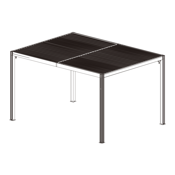
10'×13' LOUVERED PERGOLA
WITH ALUMINUM ROOF
ASSEMBLY MANUAL
MODEL#: LGMF1606B
Missing part? Damaged? Contact us via email at
service@domioutdoorliving.com
www.domioutdoorliving.com
©
Copyright 2022-2024 domi LLC. I All Rights Reserved.
Advertisement

Related Manuals for domi outdoor living LGMF1606B


Summary of Contents for domi outdoor living LGMF1606B
- Page 1 10'×13' LOUVERED PERGOLA WITH ALUMINUM ROOF ASSEMBLY MANUAL MODEL#: LGMF1606B Missing part? Damaged? Contact us via email at service@domioutdoorliving.com www.domioutdoorliving.com © Copyright 2022-2024 domi LLC. I All Rights Reserved.
- Page 2 -Maximum weight capacity is 1000 pounds. -If moderate to heavy snow is forecast, open the lovers to avoid snow accumulating.
- Page 3 10' x 13' Louvered Pergola Dimension 100X100mm (3.94"X3.94")
- Page 4 MOUNTING BLUEPRINT Pergola 10' x 13' 3032mm(119.37") 126mm(4.96") 126mm(4.96") 126mm(4.96")
- Page 5 67mm(2.64") 35mm 1.38" If the deck is hard wood and the depth of it is over 3 inch If the ground is concreted and the depth you can use 5/16 in. ×4 in. of it is over 3 inch you can use 1/4 inch Structural Wood Screw to expansion bolts to mount the pergola.
- Page 7 Step 1: Connect Part #AA and Part #Fb with 4 Bolts 1# as shown. Repeat the above procedures to assemble the other 3 posts.
- Page 8 Step 2: Insert Part #Jb into Part #B1. Secure with 2 Bolts 1# and 2 Bolts 9# as shown. Repeat the above procedures to assemble another beam.
- Page 9 Linkage Rod Step 3: Insert Part #K into the hole on Linkage Rod of Beam #B1b. Secure with Nut 6# and gasket as shown. Linkage Rod Repeat the above procedures to assemble another beam.
- Page 10 Step 4: Insert 2 Part# H into Part #B3b and Part #B4b with 12 Bolts 1# as shown. Repeat the above procedures to assemble another beam.
- Page 11 Form Main Framework Step 5: Install 8 Bolts 2# to secure Beam #B1b and Beam #B3b/B4b with Post #Aa as shown. Repeat the above procedures to assemble the other three sides. ATTENTION: Don't tighten the bolts before all bolts are in the correct place.
- Page 12 Install Center Beam Step 6: Place Part #Bb on the middle joint of Part #B3b and Part #B4b with 4 Bolts 1# as shown. Repeat the above procedures to assemble another side. Left Side Right Side...
- Page 13 Step 7: Install Part #Cb on the inside of Part #B3b with 4 Bolts 3# as shown. Repeat the above procedures to assemble another side. Section View Inside View...
- Page 14 Step 8: Install Part #G2 at the joint of Part #B3b and Part #B4b with 2 Bolts 10# as shown. Repeat the above procedures to assemble another side. Section View...
- Page 15 Linkage Rod Step 9: Linkage Rod ② Fix another part of Part #L on Part #Jb ①Insert the connecting rod end of Part #L with 2 Bolts 8#, nuts and gaskets. into Part #K and secure with 1 Nut 7# and gasket.
- Page 16 Step 10: Install Part #Eb with Bolts 10# as shown. ※ If moderate to heavy snow is forecast, pls open the louvers to avoid snow accumulating. Install Louvers...
- Page 17 Louver Close Louver Fully Louver Half State Open State Open State Step 11: Just shake the roller rod anytime you want let the sun in or block the sunray. (ATTENTION: Louvers can be opened and closed in cycles.) Please make sure that the Louvers were fully closed for waterproof effect.
- Page 18 Thanks for your purchase. At domi outdoor living, we believe in our products. That’s why we provide a 12-month warranty and friendly, casy-to-reach after-sales service. So if you have any questions about our product and assembly- ,please feel free to contact us.
Need help?
Do you have a question about the LGMF1606B and is the answer not in the manual?
Questions and answers