Table of Contents
Advertisement
Quick Links
6159932010-09
CVIC - MODCVIC - MULTICVIC
CVIC controller - Release 4.4
MODCVIC module - Release 4.4
Manual no.: 6159932010
The features and descriptions of our products are subject to change
without prior notice.
© Copyright 2007, Desoutter St Herblain France
All rights reserved. Any unauthorized use or copying of the
contents or part thereof is prohibited. This applies in particular
©
to trademarks, model denominations, part numbers and
drawings. Use only authorized parts. Any damage or
malfunction caused by the use of unauthorized parts is not
covered by Warranty or Product Liability.
Desoutter - ZAC de la Lorie - 38 rue Bobby Sands
BP 10273 - 44818 Saint-Herblain Cedex - France - www.cp.com
Advertisement
Table of Contents

Related Manuals for Desoutter CVIC


Summary of Contents for Desoutter CVIC
- Page 1 Use only authorized parts. Any damage or malfunction caused by the use of unauthorized parts is not covered by Warranty or Product Liability. Desoutter - ZAC de la Lorie - 38 rue Bobby Sands BP 10273 - 44818 Saint-Herblain Cedex - France - www.cp.com...
- Page 2 6159932010-09 CVIC - MODCVIC - MULTICVIC English 2 / 60...
-
Page 3: Table Of Contents
1 - Safety ---------------------------------------------------------------------------------------------------- 5 2 - Installation and Installation Instructions --------------------------------------------------------- 7 SECTION 2 - INTRODUCTION ---------------------------------------------------------------------------- 9 1 - CVIC Controller ---------------------------------------------------------------------------------------- 9 2 - Self-contained MODCVIC Control Module ----------------------------------------------------- 10 3 - MULTICVIC system ---------------------------------------------------------------------------------- 10 SECTION 3 - DESCRIPTION OF THE CONTROLLERS ------------------------------------------- 11 1 - CVIC controller ---------------------------------------------------------------------------------------- 11 1.1 - Mechanical features --------------------------------------------------------------------------- 11... - Page 4 3.7.2 - "REPORT OUTPUT" Menu ------------------------------------------------------- 38 3.7.3 - "BAR CODE" Menu ----------------------------------------------------------------- 39 3.8 - «CONTROLLER» Menu ---------------------------------------------------------------------- 39 SECTION 7 - MAINTENANCE OF THE CVIC CONTROLLER ----------------------------------- 41 1 - "MAINTENANCE" Menu ---------------------------------------------------------------------------- 41 1.1 - "TEST" Menu ------------------------------------------------------------------------------------ 41 1.2 - "CHANNEL TEST"...
-
Page 5: Section 1 - Warnings
6159932010-09 CVIC - MODCVIC - MULTICVIC English 5 / 60 SECTION 1 - WARNINGS 1 - Safety General Safety Instructions: WARNING! To reduce risk of injury, everyone using, installing, repairing, maintaining, changing accessories on, or working near this tool must read and understand the safety instructions before performing any such task. - Page 6 6159932010-09 CVIC - MODCVIC - MULTICVIC English 6 / 60 Remove adjusting keys or switches before turning the tool on. A wrench or a key that is left attached to a rotating part of the tool may result in personal injury.
-
Page 7: Installation And Installation Instructions
2 - Installation and Installation Instructions Mains voltage All the controllers of the range (CVIC and MODCVIC) can operate equally from 115V to 230V ± 10%/ 50 to 60Hz without adjustment and without fuse change. The CVIC controllers are supplied with single-phase current. The MODCVIC modules are supplied with three-phase current. - Page 8 6159932010-09 CVIC - MODCVIC - MULTICVIC English 8 / 60 General instructions: All connections between the filter and the servodrives shall be provided by means of shielded cables. At the passage of these cables through an electrical component (contactor, circuit-breaker, etc.), ground the shielding as shortly as possible through a grounding rod.
-
Page 9: Section 2 - Introduction
1 - CVIC Controller The CVIC controller is available in normal mode and in ECPHT mode (high run down speed and a high torque). The normal mode covers two controller models (-2 and -4) in two versions each (L and H). -
Page 10: Self-Contained Modcvic Control Module
Number of stored results 2 - Self-contained MODCVIC Control Module The MODCVIC is the rackable version of the CVIC controller. Two models are available: MODCVIC-2 and MODCVIC-4 and two versions: «L» and «H». Without keyboard or display, the MODCVIC must be connected to a PC, temporarily for programming, data transfer and retrieval of tightening results and permanently to display its real time operation. -
Page 11: Section 3 - Description Of The Controllers
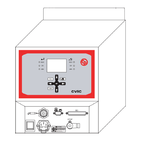
6159932010-09 CVIC - MODCVIC - MULTICVIC English 11 / 60 SECTION 3 - DESCRIPTION OF THE CONTROLLERS 1 - CVIC Controller 1.1 - Mechanical Features Weight 5.800g. To reduce the risk of injury, user must read and understand instruction manual. -
Page 12: Example: Setting The Date And Time
6159932010-09 CVIC - MODCVIC - MULTICVIC English 12 / 60 Description of the keys - to scroll through a menu. - to scroll through a data entry screen. - to increment digits in digital entry mode. - to scroll through a (lozenge-tagged) list. -
Page 13: Bottom Front Panel
6159932010-09 CVIC - MODCVIC - MULTICVIC English 13 / 60 1.5 - Bottom Front Panel SubD 9 points: PC connection, Bar code or printer PC cable: P.N. 6159170470. Printer cable: P.N. 6159170110. The bar code is supplied with its cable. -
Page 14: Description Of The Front Panel
6159932010-09 CVIC - MODCVIC - MULTICVIC English 14 / 60 2.2 - Description of the Front Panel Ph.1 PC/bar code/printer Torque/angle reports Ph.2 5 V voltage on Ph.3 READY Power voltage on Servodrive ready Module on Ncycle OK Tool connection... -
Page 15: Slave Modcvic Module
6159932010-09 CVIC - MODCVIC - MULTICVIC English 15 / 60 3.1 - Slave MODCVIC Module This controller has the same features as the self-contained MODCVIC but it is fitted with a network board to allow interaction with the master CPUCVIC module. -
Page 16: Cpucvic Module
6159932010-09 CVIC - MODCVIC - MULTICVIC English 16 / 60 3.2 - CPUCVIC Module 3.2.1 - Description of the CPUCVIC Rack n e t w o r k a d d r e s s m a i n p o w e r... -
Page 17: Cpucvic Leds
6159932010-09 CVIC - MODCVIC - MULTICVIC English 17 / 60 3.2.3 - CPUCVIC LEDs The LEDs show the operation of the slave MODCVICs that are connected: ready to operate motor running torque and angle within tolerances M A X error different from «torque and angle out of tolerances»... - Page 18 6159932010-09 CVIC - MODCVIC - MULTICVIC English 18 / 60...
-
Page 19: Section 4 - Start-Up
When switched on, the controller automatically detects the correct operation of the tool and of the controller itself. If everything is OK, the control screen is displayed by the CVIC. If a problem occurs when the controller is switched on, the screen displays the message: «NOT READY». -
Page 20: Setting The Date And Time
6159932010-09 CVIC - MODCVIC - MULTICVIC English 20 / 60 2.5 - Setting the Date and Time - Menu: MAIN\SERVICE\DATE. - Allows you to select the format: (DD/MM/YY, MM/DD/YY, YY/MM/DD). - Setting the date. - Setting the time. 2.6 - Selecting the controller mode Enter the station menu and select the mode according to the tool you want the controller to run: - If ECPHT tools are used, select the ECPHT mode. -
Page 21: Section 5 - Programming The Version "L" Controller
6159932010-09 CVIC - MODCVIC - MULTICVIC English 21 / 60 SECTION 5 - PROGRAMMING THE VERSION «L» CONTROLLER 1 - «CONTROL» Menu When the controller is switched on, the control screen is displayed by default. This screen displays the tightening report and the target torque instruction which can be changed directly on the screen. -
Page 22: Parameters" Menu
In the version L CVIC, the tightening cycle is stored in the tool memory and corresponds to cycle «0» (zero). It can include 3 phases: approach, run down speed and final speed phase. Only the run down speed and final speed phases are optimised automatically with the «Learning»... -
Page 23: Pc Link" Menu
6159932010-09 CVIC - MODCVIC - MULTICVIC English 23 / 60 Err.Ack. Yes/No (to validate start cycle after a reject report). Push Start (no by default). When this function is enabled (yes), the tool «Push Start» is inhibited. The tool is started either by pressing the lever or enabling the external start input. - Page 24 6159932010-09 CVIC - MODCVIC - MULTICVIC English 24 / 60...
-
Page 25: Section 6 - Programming The Version "H" Controller
6159932010-09 CVIC - MODCVIC - MULTICVIC English 25 / 60 SECTION 6 - PROGRAMMING THE VERSION «H» CONTROLLER This section explains how you can change the default settings in the main menus of the controller. 1 - «CONTROL» Menu Screen no. 1 Screen no. -
Page 26: Parameters" Menu
6159932010-09 CVIC - MODCVIC - MULTICVIC English 26 / 60 3 - «PARAMETERS» Menu The «PARAMETERS» menu allows you to: - display the tool features «SPINDLE» menu - change the programming of a cycle in detail «CYCLES» menu - quickly program a cycle «QUICK CYCLES»... -
Page 27: Programming The Phases
6159932010-09 CVIC - MODCVIC - MULTICVIC English 27 / 60 3.2.3 - Programming the Phases After selecting a cycle, the cursor will move to the line where the various phases of the selected cycle are shown. You will be allowed to modify, insert or delete a phase. - Page 28 6159932010-09 CVIC - MODCVIC - MULTICVIC English 28 / 60 Programming the parameters Using , position the cursor on the phase whose parameters you want to program. Press Search Sequence Phase (H) The maximum time is simply displayed for the Search sequence phase as it is implicitely equal to the number of rotations multiplied by the rotation time + stop time.
- Page 29 6159932010-09 CVIC - MODCVIC - MULTICVIC English 29 / 60 Run Down Speed Phase (L - H) in normal mode Max.time maximum phase running time. 0.01 - 99 s. Int.time time programmed between this phase and the next one: 0 - 20 s.
- Page 30 6159932010-09 CVIC - MODCVIC - MULTICVIC English 30 / 60 Press Motor settings: «MOTOR PARAM.» Thread Right/Left. Speed rotational speed: 0 - 100 %. Acceler 0 - 20 s. Acceleration or deceleration time to switch from one speed to another. This parameter is enabled for the first phase and when the interphase time is not equal to zero.
- Page 31 6159932010-09 CVIC - MODCVIC - MULTICVIC English 31 / 60 Press Motor settings: «MOTOR PARAM.» Thread Right/Left. Speed rotational speed: 0 - 100 %. Acceler 0 - 20 s. Acceleration or deceleration time to switch from one speed to another. This parameter is enabled for the first phase and when the interphase time is not equal to zero.
-
Page 32: Quick Cycles" Menu
6159932010-09 CVIC - MODCVIC - MULTICVIC English 32 / 60 Synchro Waiting Phase (H) This phase allows you to synchronise the phases of several controllers. To synchronise several controllers, you must program a waiting phase for each controller and use the «synchro» signals (see Input/Output section). -
Page 33: Learning" Menu
6159932010-09 CVIC - MODCVIC - MULTICVIC English 33 / 60 Press then to select the type of phase and press to validate. Press again to describe the contents of the phase. Press to validate the changes. To insert a phase into the list, use the «Ins» function. -
Page 34: Input / Output Configuration
6159932010-09 CVIC - MODCVIC - MULTICVIC English 34 / 60 Screen By default Comments Lock.NOK lock N cycles OK: when this function is enabled, the system locks the start cycle as soon as the number of cycles run with an accept report has reached the programmed «NCYCOK». -
Page 35: Description Of Inputs
PLC output, CVIC input wiring Two configurations are available: A) The CVIC 24 V (contacts 17 and 20) is used as the B) By default, the PLC 24 V is sent to the inputs of the «common» of a PLC relay board. -
Page 36: Description Of Outputs
OK. CVIC output, PLC input wiring Below are shown the two wiring configurations available for the relayed outputs of the CVIC: A) The PLC 24 V is connected to the CVIC output B) The CVIC 24 V is connected to the output common. - Page 37 6159932010-09 CVIC - MODCVIC - MULTICVIC English 37 / 60 Default configuration Specific configuration Input Input Output Logic Output 0 V (+24 V) 0 V (+24 V) +24 V controller (700 mA max) +24 V controller (700 mA max) READY...
-
Page 38: Peripherals" Menu
6159932010-09 CVIC - MODCVIC - MULTICVIC English 38 / 60 3.7 - «PERIPHERALS» Menu 3.7.1 - «SERIAL PORT» Menu The serial port is used for the following functions: ♦ Downloading to PC, ♦ Bar code and report output, ♦ Printing the results in order of occurrence (ASCII), ♦... -
Page 39: Bar Code" Menu
6159932010-09 CVIC - MODCVIC - MULTICVIC English 39 / 60 3.7.3 - «BAR CODE» Menu The bar code reader allows you to automatically select one of the cycles previously programmed in the controller. To enable the bar code reader, you need to do the following: - declare the source of selection of the cycles as being the bar code. - Page 40 6159932010-09 CVIC - MODCVIC - MULTICVIC English 40 / 60...
-
Page 41: Section 7 - Maintenance Of The Cvic Controller
6159932010-09 CVIC - MODCVIC - MULTICVIC English 41 / 60 SECTION 7 - MAINTENANCE OF THE CVIC CONTROLLER This section helps the maintenance operator to: - check that the controller+tool assembly operates correctly. - know the number of cycles run. -
Page 42: Calibration" Menu
If the measuring unit is not correctly connected or programmed, an error message «Wait. for conn.» is displayed on the screen. Follow the instructions displayed on the CVIC screen. 10 tests can be run and they are performed at various increasing speeds. Run one test after another. -
Page 43: Changing The Memory Battery
6159932010-09 CVIC - MODCVIC - MULTICVIC English 43 / 60 1.5 - Changing the Memory Battery Memory battery connection: the memory battery allows you to save the parameters and results in of mains power failure. A maximum lifetime of 10 years is indicated in the manufacturer’s specifications. For safety purposes, it is recommended to change the battery every 5 years. -
Page 44: Service" Menu
6159932010-09 CVIC - MODCVIC - MULTICVIC English 44 / 60 2 - «SERVICE» Menu 2.1 - «CONTRAST» Menu Press to adjust the contrast of the display. When the adjustment of the contrast is such that it no longer allows you to display the menus, the following procedure... -
Page 45: Appendix - Pc Wiring Diagram
B L A C K B L A C K G N D Appendix - Synchronising several CVIC controllers To synchronise several CVIC version «H» controllers, you must: - allocate the synchro in and synchro out signals to unused inputs and Controller 1 outputs. -
Page 46: Appendix - Ec, Mc And Ec/Mc Extension Wiring Diagram
6159932010-09 CVIC - MODCVIC - MULTICVIC English 46 / 60 Appendix - EC, MC and EC/MC extension wiring diagram 1 2 p o i n t c o n t a c t p i n 1 2 p o i n t c o n t a c t s o c k e t... -
Page 47: Appendix - Printing Format Of Tightening Results
6159932010-09 CVIC-MODCVIC-MULTICVIC English 47 / 60 Appendix - Printing Formats for tightening results PC2 FORMAT: 1 char. <CR> range or cycle number fastener number «T=+» torque in 1/10 of Nm <LF> “ “ <CR> range or cycle number fastener number «A=+»... - Page 48 6159932010-09 CVIC-MODCVIC-MULTICVIC English 48 / 60 According to the various combinations, the following characters will be obtained: accept torque accept angle min. torque accept angle max. torque accept angle accept torque min. angle min. torque min. angle max. torque min. angle accept torque max.
- Page 49 6159932010-09 CVIC-MODCVIC-MULTICVIC English 49 / 60 PC5-A FORMAT: start of frame character report (in hexadecimal notation): angle report in binary notation torque report Report per spindle: torque, angle where AA or TT = if low report if accept report if high report e.g.: if accept report for all the spindles...
- Page 50 6159932010-09 CVIC-MODCVIC-MULTICVIC English 50 / 60 PC5-B FORMAT: start of frame character report (in hexadecimal notation): see PC5A where TT or AA = Report per spindle if low report (torque, angle) if accept report if high report e.g.: if accept report for all the spindles...
- Page 51 6159932010-09 CVIC-MODCVIC-MULTICVIC English 51 / 60 target angle in 1/10th of degree (ASCII notation) e.g.: 105.0° 30 31 30 35 30 Available parameters programmed for 1 spindle (x times the number of spindles) maximum angle in 1/10th of degree (ASCII notation) e.g.: 110.0°...
- Page 52 6159932010-09 CVIC-MODCVIC-MULTICVIC English 52 / 60...
-
Page 53: Appendix - Tightening Strategies
6159932010-09 CVIC-MODCVIC-MULTICVIC English 53 / 60 Appendix - Tightening Strategies T o r q u e T a r g e t t o r q u e Torque-controlled tightening M a x T a r g e t M i n The recorded value is: the peak torque Spindle stop if torque ≥... - Page 54 6159932010-09 CVIC-MODCVIC-MULTICVIC English 54 / 60 A n g l e T o r q u e Angle + torque controlled tightening M a x the recorded values are the following: F i n a l t o r q u e...
- Page 55 6159932010-09 CVIC-MODCVIC-MULTICVIC English 55 / 60 Torque + angle controlled untightening In addition to monitoring the untightening of the fastener, the system monitors the number of degrees reached while maintaining a residual torque in the fastener. S a f e t y t o r q u e The control phase starts IF torque >...
- Page 56 6159932010-09 CVIC-MODCVIC-MULTICVIC English 56 / 60...
-
Page 57: Appendix - Cycle Flowchart And Timing Chart
6159932010-09 CVIC-MODCVIC-MULTICVIC English 57 / 60 Appendix - Cycle flowchart and timing chart 1 - Cycle flowchart S t a r t R e a d y = 1 Y e s E x t e r n a l r e s e t R e s e t = 1 A c c e p t r e p o r t &... - Page 58 6159932010-09 CVIC-MODCVIC-MULTICVIC English 58 / 60 2 - Cycle timing chart r e a d y c y c l e 1 c y c l e 2 c y c l e 4 c y c l e a c k n o w . 1 c y c l e a c k n o w .
-
Page 59: Appendix - Cvic Report Codes
The CVIC correctly measures the torque when the tool runs at constant speed. The 1.6 software version detects this and displays the “Err” message in case of non constant speed when the torque is reached. - Page 60 Tool memory parameter reading is impossible. Out of range The connected tool is not compatible with the CVIC model (e.g.: ECA60 connected to CVIC-2). Controller busy (for example, down-loading or up-loading in progress). Batch of cycles complete (number of cycles OK) tool is disabled if the box "lock on NCYOK" (lock after a batch of cycle complete) in the "STATION"...
Need help?
Do you have a question about the CVIC and is the answer not in the manual?
Questions and answers