Desoutter CVIL II Operator's Manual
Hide thumbs
Also See for CVIL II:
- Manual (36 pages) ,
- Quick start manual (57 pages) ,
- Original instructions manual (75 pages)
Table of Contents
Advertisement
Quick Links
Download this manual
See also:
Manual
Model
Part number
CVIL II
6159326800
Original instructions.
©
Copyright 2018, Ets Georges Renault 44818 St Herblain, FR
All rights reserved. Any unauthorized use or copying of the contents or part thereof is
prohibited. This applies in particular to trademarks, model denominations, part numbers
and drawings. Use only authorized parts. Any damage or malfunction caused by the use of
unauthorised parts is not covered by Warranty or Product Liability.
CVIL II Controllers
V 5.1.X
Operator's manual
Part no
6159933780
Issue no
09
Date
01/2018
Page
1 / 80
www.desouttertools.com
Advertisement
Table of Contents

Subscribe to Our Youtube Channel
Related Manuals for Desoutter CVIL II


Summary of Contents for Desoutter CVIL II
- Page 1 Part no 6159933780 Issue no Date 01/2018 Page 1 / 80 CVIL II Controllers V 5.1.X Operator’s manual Model Part number CVIL II 6159326800 Original instructions. © Copyright 2018, Ets Georges Renault 44818 St Herblain, FR All rights reserved. Any unauthorized use or copying of the contents or part thereof is prohibited.
-
Page 3: Table Of Contents
5.3 - Inputs / Outputs ........... 15 2 - INTRODUCTION ........5 5.4 - Barcode reading .......... 15 2.1 - CVIL II range ..........5 5.5 - Maintenance request ........16 2.2 - Number of cycle and phases ......5 5.6 - Number of pulses during the cycle .... - Page 4 11.4.1 - Main phase: Seating detection ....... 62 8.3.1 - Changing the memory battery ......50 11.4.2 - Second phase: Post-seating ......62 8.3.2 - Desoutter Tool and Account Services ....50 11.5 - Stall torque controlled tightening ....63 8.4 - Spare parts ..........51 11.6 - Prevailing torque control ......
-
Page 5: Safety Instructions
ERAL 2 - INTRODUCTION In-line ERDL ERPL 2.1 - CVIL II range The CVIL II controller can control 1 portable ER and ERA Pistol grip ERPS type and/or fixed EME type and/or portable ELRT type ERPLT electric power tool. It is supplied ready to operate. -
Page 6: Main Differences Between Versions
CVIL II controllers. CVIPC 2000 can be installed on standard PCs running Windows 2000, XP or Vista and communicates with CVIL II controller via ethernet TCP/IP or RS232 port. The real time monitoring functions include access to Cpk, curves, operator monitor, etc. -
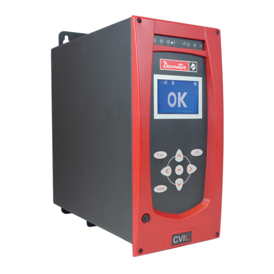
Page 7: Description
6159933780 CVIL II Issue no: 09 3 - DESCRIPTION 3.4 - Front panel 3.1 - Delivered equipment Legend CVIL II box Quick start manual Input / Output connector with "stop" jumper Safety manual 3.2 - Dimensions 1 3 0 Legend... -
Page 8: Bottom Panel
6159933780 CVIL II Issue no: 09 3.5 - Bottom panel Legend RS232 port, SubD 9 points - PC cable ref.: 6159170470 - Printer cable ref.: 6159170110 - BRDx2 ref.: 6159363280 Ethernet port 8 inputs / 8 Outputs connector for PLC or indicator box... -
Page 9: Initial Start Up
"Safety instructions", page 5. 4.1.1 - STOP signal CVIL II controllers are equipped of redundant emergency "STOP" signals which provide a high level of reliability to this function (Category 2, level "d" according ISO 13849 standard). -
Page 10: Switch Off
● Preferably use the longest length of extension cable and the shortest length of tool cable. ● In case of failure when implementing the extension cables, contact your local Desoutter representative for more information. 4.1.3 - Wall mounting fixation Ø6.5 Ød D >... -
Page 11: 115/230 Vac Cable Connection
6159933780 CVIL II Issue no: 09 4.2 - Start up 4.1.5 - 115/230 VAC cable connection When switched on, the controller automatically detects the correct operation of the tool and of the controller itself. If everything is OK, the control screen is displayed by the CVIL II. -
Page 12: Language Selection
6159933780 CVIL II Issue no: 09 4.2.2 - Language selection 4.2.3 - Setting the date and time 12 / 80 01/2018... -
Page 13: Contrast Adjustment
6159933780 CVIL II Issue no: 09 4.2.4 - Contrast adjustment 4.2.5 - Access code The access code is used to protect the controller against any keying error. At the time of delivery, no code is programmed; the icon is displayed on the screen. -
Page 14: Activation Code
6159933780 CVIL II Issue no: 09 4.2.6 - Activation code 8 alphanumerical characters maximum. ● Press to write (1). ● Press to validate. ● Press to position the cursor under the next character (2). Lock access by entering your code again. The padlock icon will lock meaning that writing is prohibited. -
Page 15: Control Screens
6159933780 CVIL II Issue no: 09 5 - CONTROL SCREENS 5.1 - Standard screen Legend Counter Status of the NcyOK counter Tightening results Detailed tightening report Min. torque Max. torque This screen displays the tightening results of the last run cycle (3), the detailed tightening report (4) and the status of the NcyOK counter (2). -
Page 16: Maintenance Request
6159933780 CVIL II Issue no: 09 5.5 - Maintenance request This icon will blink on the Control screen when the maintenance is ON. Refer to chapter 8.3.8.1 – Maintenance info screen. 5.6 - Number of pulses during the cycle In the Pulse mode, the number of pulses done during the cycle is displayed on the lower left of the screen. -
Page 17: Results
6159933780 CVIL II Issue no: 09 6 - RESULTS This menu allows you to display and delete the tightening results. 01/2018 17 / 80... -
Page 18: Programming
6159933780 CVIL II Issue no: 09 7 - PROGRAMMING 7.2 - LEARNING menu This is a very simple and fast way and to program a 7.1 - CYCLES and PARAMETERS menu cycle for non expert people. The controller adapts automatically speeds and all other The CYCLES menu allows you to: parameters by analysing the joint. -
Page 19: Cycles Menu
6159933780 CVIL II Issue no: 09 7.3 - CYCLES menu 7.3.1 - Introduction The CYCLES menu allows you to change or create the programming of the cycles. A tightening cycle consists of a sequence of phases run consecutively. Each phase is defined by main parameters and tightening instructions according to the selected type of tightening and motor settings. -
Page 20: Selecting The Cycle
6159933780 CVIL II Issue no: 09 7.3.2 - Selecting the cycle 7.3.3 - Cycle general parameters Legend Action on NOK Parameters cycle 7.3.3.1 - Programming the action on NOK for each cycle Associated with the cycle, this menu allows you to detect anomalies at various stages of the tightening cycle. - Page 21 6159933780 CVIL II Issue no: 09 Select the relevant action: 7.3.3.2 - Parameters cycle (in Normal mode) Parameter Comment Unused The option is disabled. Stop cycle As soon as one of the torque or angle parameters is out of tolerances at the end of one of the phases, the cycle stops at the end of this phase.
-
Page 22: Programming The Phase
6159933780 CVIL II Issue no: 09 7.3.3.3 - Parameters cycle (in Pulse mode) 7.3.4 - Programming the phase After selecting a cycle, the cursor will move to the line where the various phases of the selected cycle are shown. You will be allowed to modify, insert or delete a phase. -
Page 23: Programming The Parameters
6159933780 CVIL II Issue no: 09 7.3.4.2 - Inserting a phase 7.3.5 - Programming the parameters ● Create a blank before the phase before which you ● Using , position the cursor on the phase want to insert a new phase: whose parameters you want to program. - Page 24 6159933780 CVIL II Issue no: 09 7.3.5.3 - Final Speed Phase Parameter Comment (Normal mode and Pulse mode) Power 1 - 100% No result for this phase. 7.3.5.2 - Run Down Speed Phase (Normal mode and Pulse mode) Parameter Comment...
- Page 25 6159933780 CVIL II Issue no: 09 7.3.5.5 - Run reverse phase Parameter Comment (Normal mode and Pulse mode) Stall time 0.000 - 9.990 seconds. Other... See motor parameters Detailed RP: See "Tightening strategy guide", page 60. 7.3.5.4 - Action on NOK Phase (Normal mode and Pulse mode) When a report is rejected (max.
- Page 26 6159933780 CVIL II Issue no: 09 7.3.5.6 - Motor parameters (Normal mode) 7.3.5.7 - Motor parameters (Pulse mode) Parameter Comment Parameter Comment Thread Right / Left. Bandwidth adjustment from 4 to 512 Hz. Reset The Reset function allows you to reset 128 Hz by default.
- Page 27 6159933780 CVIL II Issue no: 09 7.3.5.8 - Jump to another phase (Normal mode and Pulse mode) This phase allows you to design more sophisticated cycles. For example: D F1 V1 F2 — F3 J1 Phase 1 Run down speed...
-
Page 28: Sequence Menu
A sequence is a chain of cycles. This phase allows you to synchronize the phases of The CVIL II can comprise one sequence only and this several controllers. To synchronize several controllers, sequence can be made up of 8 cycles as a maximum. -
Page 29: Quick Cycles Menu
6159933780 CVIL II Issue no: 09 7.5 - QUICK CYCLES menu This menu allows you to quickly program the cycles. By default, the quick cycles consist of a run down speed and final speed phase. The operator only programs the target torque and the maximum angle on the screen. -
Page 30: Spindle Menu
6159933780 CVIL II Issue no: 09 7.6 - SPINDLE menu 7.7 - STATION menu This menu displays controller and tool identification and characteristics. 30 / 80 01/2018... -
Page 31: Station - General Parameters
6159933780 CVIL II Issue no: 09 7.7.1 - STATION – General parameters Screen name By default Comment Name Possibility to associate a name to the station. Station Enter a comment. comment Mode Normal Normal/Pulse Enter Pulse mode for ELRT tools - and Normal mode for all other tools. - Page 32 6159933780 CVIL II Issue no: 09 Screen name By default Comment Scy pulse Start cycle by pulses: the Start Cycle signal can be activated with a pulse. For safety purposes, this parameter is only available on fixed spindles. Warning: It is strongly advised against programming the SCY pulse option if handheld tools are used.
-
Page 33: Input / Output Configuration
6159933780 CVIL II Issue no: 09 7.7.2 - INPUT / OUTPUT configuration The STATION menu also allows you to reconfigure the addresses of the input and output functions on the I/O connector. According to the desired operation, you can use either the default configuration, or the dedicated configuration with functions not defined in the default configuration. -
Page 34: Input Menu
6159933780 CVIL II Issue no: 09 7.7.3 - INPUT menu Do not change SCY and DIR settings. Inputs Name Factory Comments config. Cycle 1 selection CYC1 Binary coding - weight 1, i.e. from 0 to 1. Cycle 2 selection CYC2 Binary coding - weight 2, i.e. - Page 35 6159933780 CVIL II Issue no: 09 Inputs Name Factory Comments config. Synchronization SYNC Validates the synchronization of the tightening phases of several controllers (see "Synchronizing several cvil controllers", page 52). Quick stop 2 STOP2 This input is not configurable. This is the redundant input of STOP1 (see "STOP signal", page 9).
-
Page 36: Output Menu
6159933780 CVIL II Issue no: 09 7.7.4 - OUTPUT menu Outputs Name Factory Comments config. Cycle 1 CYC1 Binary coding -weight 1. The cycle acknowledgement is sent back only if it corresponds to a programmed cycle; otherwise it is at "0". - Page 37 6159933780 CVIL II Issue no: 09 7.7.4.1 - CVIL output, PLC input wiring Below are shown the two wiring configurations available for the relayed outputs of the CVIL. ● The PLC 24V is connected to the CVIL output common. The PLC input do not receive external 24V.
-
Page 38: Run Reverse Menu
6159933780 CVIL II Issue no: 09 7.8 - PERIPHERALS menu 7.7.5 - RUN REVERSE menu Parameters Comments Tool En. Rev. ● Yes: the operator cannot perform a loosening operation unless the SPVALRV (spindle reverse validation) input is activated. ● No: the operator is allowed to perform a loosening operation. -
Page 39: Ethernet Configuration Menu
6159933780 CVIL II Issue no: 09 7.8.2 - ETHERNET CONFIGURATION menu 7.8.3 - ETHERNET SOCKET 1 menu The ethernet socket 1 is used for the following function: Parameter Comment ● PC transfer (used to communicate with CVIPC 2000 IP Address... -
Page 40: Ethernet Socket 3 Menu
6159933780 CVIL II Issue no: 09 7.8.5 - ETHERNET SOCKET 3 menu 7.8.6.2 - Profinet IO module Parameter Comment The ethernet socket 3 is used for the following functions: ● Open Protocol. IP Address IP address of the controller in the PLC network (must differ from ●... -
Page 41: Report Output Menu
6159933780 CVIL II Issue no: 09 7.8.6.4 - Reset a dynamic mapping 7.8.8 - BAR CODE menu Any standard dynamic mapping can be reset. Check that a Fieldbus module is connected to the controller. ● Go to "Parameters/Peripherals/PLC". ● Press the keys "Up/Left/Down/Right/Enter" one after the other. -
Page 42: Cvinet Menu
6159933780 CVIL II Issue no: 09 7.8.9 - CVINET menu Parameter Comment FIFO blocking When the result memory to be transmitted is full, the start cycle that follows can be locked or not (the start cycle is not locked on, but next results are not saved). -
Page 43: Toolsnet Menu
6159933780 CVIL II Issue no: 09 7.8.10 - TOOLSNET menu Parameter Comment System type Type of system for ToolsNet server (3 is the default: OP Undefined controller). System Identification of the system in the controller network (group of stations). number... -
Page 44: Controller Menu
6159933780 CVIL II Issue no: 09 7.9 - CONTROLLER menu Parameter Comments Comment Possibility to add a comment up to 15 characters to identify the controller. Possibility to add a comment or figures up to 3 characters to identify the fastener. -
Page 45: Curves Menu
6159933780 CVIL II Issue no: 09 7.10 - CURVES menu Parameter Comment Durat Recording time. Thresh Threshold = 0: The curve is displayed back from motor stop for the recording time. Threshold > 0: The curve is displayed from the defined torque threshold and for the recording time. -
Page 46: Maintenance
6159933780 CVIL II Issue no: 09 8 - MAINTENANCE 8.1.1.1 - START SPINDLE menu This section helps the maintenance operator to: ● Check that the controller + tool assembly operates correctly. ● Know the number of cycles run. ● Tune the system manually or automatically. -
Page 47: Channel Test Menu
6159933780 CVIL II Issue no: 09 8.1.1.3 - LEDS TEST menu 8.1.3 - COUNTERS menu 8.1.3.1 - Tool and controller counters This menu allows for testing the LEDs located on the front side of the CVIL and for testing the LEDs on the tool. -
Page 48: Calibration Menu
The torque transducer inserted in line with the tool can be connected to any measuring unit in the Desoutter range. Run a tightening cycle 5 times and manually enter the values read on the standard instrument. -
Page 49: Options
8.1.4.2 - Calibration service 8.1.6.2 - Restore For full certified calibration, to cover your quality systems needs please consult your local Desoutter Customer Service Center that are fully prepared to support you, either at your site or in one of our workshops. -
Page 50: Maintenance Operation
CVIL II Issue no: 09 8.3 - Maintenance operation 8.3.2 - Desoutter Tool and Account Services The performance of your industrial tools directly affects 8.3.1 - Changing the memory battery the quality of your products and the productivity of your... -
Page 51: Spare Parts
Full service plans are available for single facilities or for multiple plants, whether in a single country, region or around the world. Desoutter will provide you with a full cost analysis and return of investment to ensure that you get the best optimization for taking care of your equipment. -
Page 52: Connections
6159933780 CVIL II Issue no: 09 9 - CONNECTIONS 9.1 - PC wiring diagram ● number 6159170470 1 - DCD 1 - DCD 2 - RD 2 - RD 3 - TD 3 - TD 4 - DTR 4 - DTR... -
Page 53: Tool Cables
6159933780 CVIL II Issue no: 09 9.3 - Tool cables 9.3.1 - ER cable Phase 1 Phase 1 Legend Tool side connector Phase 3 Phase 3 Controller side connector Phase 2 Phase 2 Ground Ground Black (AWG32) Blue White A GND... -
Page 54: Eme Cable
6159933780 CVIL II Issue no: 09 9.3.2 - EME cable Phase 1 Phase 1 Legend Tool side connector Phase 3 Phase 3 Controller side connector Phase 2 Phase 2 Ground Ground Blue White A GND A GND Green / Yellow... -
Page 55: Er / Eme Extension Cable
6159933780 CVIL II Issue no: 09 9.3.3 - ER / EME extension cable Legend Phase 1 Phase 1 Tool side connector Phase 3 Phase 3 Controller side connector Phase 2 Phase 2 Ground Ground Blue White A GND A GND... -
Page 56: Printing Format For Tightening Results
6159933780 CVIL II Issue no: 09 10 - PRINTING FORMAT FOR 10.2 - PC3 format TIGHTENING RESULTS Char Designation number 10.1 - PC2 format char. A (frame type) Char station number (1 to 250) Designation number port number (1 to 32) char. -
Page 57: Pc4 Format
6159933780 CVIL II Issue no: 09 10.3 - PC4 format 10.3.2.1 - Report code (See "Report codes", page 67). 10.3.1 - Title The codes emitted on letters are used for digital report outputs or printouts. Char number Designation (*) All these codes correspond to specific displays. -
Page 58: Pc5-A Format
6159933780 CVIL II Issue no: 09 10.4 - PC5-A format 10.5 - PC5-B format 10.4.1 - Report per spindle: torque rate, torque, 10.5.1 - Report per spindle: torque, angle, angle torque rate Char Designation Char Designation start of frame character... -
Page 59: Available Parameters Programmed For
6159933780 CVIL II Issue no: 09 10.5.2 - Available parameters programmed for 1 10.5.3 - Results of spindle 1 spindle (x times the number of spindles) (x times the number of spindles) Char Designation Char Designation spindle number in BCD... -
Page 60: Tightening Strategy Guide
6159933780 CVIL II Issue no: 09 11 - TIGHTENING STRATEGY GUIDE 11.1.2 - Pulse mode (hybrid) The "Torque control" strategy is effective only with joint 11.1 - Torque control from 0° to 200°. It offers the insurance that the torque has really been applied to the assembly but does not give the complete 11.1.1 - Normal mode (continuous) -
Page 61: Torque Control And Angle Monitoring
6159933780 CVIL II Issue no: 09 11.2 - Torque control and angle monitoring 11.2.2 - Pulse mode (hybrid) Torque control strategy coupled with a torque and angle 11.2.1 - Normal mode (continuous) monitoring is adapted for most assemblies in pulse mode. -
Page 62: Angle Control And Torque Monitoring
Issue no: 09 11.3 - Angle control and torque monitoring 11.4.1 - Main phase: Seating detection For CVIL II this strategy allows to rotate by N degrees a bolt over the angle threshold. This strategy improves the tension control into the bolt compare to torque control strategy. -
Page 63: Stall Torque Controlled Tightening
6159933780 CVIL II Issue no: 09 11.5 - Stall torque controlled tightening 11.6 - Prevailing torque control This tightening strategy is used to check the tuning of In the Pulse mode, the prevailing torque a tightening unit in static mode with the possibility of parameter cannot be higher than the tool max monitoring the linearity of its torque transducer. -
Page 64: Loosening - Torque Control And Angle Monitoring
6159933780 CVIL II Issue no: 09 11.7 - Loosening - torque control and angle monitoring Loosening with torque control is used when you want to maintain small constraints in the assembly. The un-tightening operation is not complete. In addition to monitoring the untightening of the fastener, the system monitors the number of degrees reached while maintaining a residual torque in the fastener. -
Page 65: Cycle Flow Chart And Timing Chart
6159933780 CVIL II Issue no: 09 12 - CYCLE FLOW CHART AND TIMING 12.2 - Cycle timing chart CHART Ready 12.1 - Cycle flow chart Cycle 1 Cycle 2 Start Cycle 4 Cycle acknowl. 1 Ready = 1 Cycle acknowl. 2 Cycle acknowl. -
Page 66: Timing Chart When Using A Crowfoot Tool
6159933780 CVIL II Issue no: 09 12.3 - Timing chart when using a crowfoot tool Start cycle Cycle in progress Screwdriver status Report Reset Nutrunner LEDs Display result Controller LEDs NCYOK A : Tightening (n) B : Indexing (n) C : Tightening (n+1) -
Page 67: Trouble Shooting Help
6159933780 CVIL II Issue no: 09 13 - TROUBLE SHOOTING HELP 13.1 - Warning Choose one of these 2 methods to look for information in this document: ● Locate the error message(s) displayed on the screen of the controller among the messages listed in the document. - Page 68 6159933780 CVIL II Issue no: 09 Text Comments QuickStop 1 ● Inform that the input Emergency STOP1 is activated. To run the tool, the controller needs both Emergency STOP1 & Emergency STOP2 inactive. QuickStop 2 ● Inform that the input Emergency STOP2 is activated. To run the tool, the controller needs both Emergency STOP1 &...
- Page 69 6159933780 CVIL II Issue no: 09 Text Comments Imax The cycle was aborted because the maximum tool current is reached. This over consumption may also be due to short-circuit, a cable fault, a resolver fault or an offset resolver fault.
- Page 70 6159933780 CVIL II Issue no: 09 Text Comments Spindle is disabled after a Reject report. If the Stop on bad report box in the STATION menu is activated, then the tool will be disabled. To enable it, it is necessary to activate the Failure acknowledge input on the I/O port.
-
Page 71: Operating Problems Due To Adjustment Problems
6159933780 CVIL II Issue no: 09 13.3 - Operating problems due to adjustment problems Symptoms Possible causes N° Check The tool starts then stops The "stall torque" instruction is 01 Check the values programmed for the run immediately without running too low. - Page 72 6159933780 CVIL II Issue no: 09 Symptoms Possible causes N° Check The angle displayed by the The gear ratio coefficient of X1 This coefficient should be equal to 1, except controller is different from the the tool has been updated by in the case of additional reduction gears.
-
Page 73: Operating Problems Due To Wear Or Breakdown
6159933780 CVIL II Issue no: 09 13.4 - Operating problems due to wear or breakdown Symptoms Possible causes N° Check The tool does not start whether The controller is switched off 11 Check: in tightening, or run reverse ● The condition of the On/Off switch of the mode.The screen is idle. - Page 74 6159933780 CVIL II Issue no: 09 Symptoms Possible causes N° Check The tool does not always start. Faulty contact in the trigger 21 In the "Maintenance - Inputs/Outputs" menu, switch. check the switching of the concerned input. If there is a fault, please contact your local customer center.
-
Page 75: Glossary
6159933780 CVIL II Issue no: 09 14 - GLOSSARY Acceleration rate This is the time expressed in seconds for the tool to switch from the initial speed (the speed during the previous phase) to the speed requested in the next phase. The acceleration rate characterizes the acceleration or deceleration of the tool. - Page 76 6159933780 CVIL II Issue no: 09 Power This is the word used to define the maximum current and therefore the maximum torque allowed in a phase. It is expressed as a percentage of the maximum current for a given tool.For instance, 100% corresponds to the full power available to run a phase.
- Page 77 6159933780 CVIL II Issue no: 09 01/2018 77 / 80...
- Page 78 6159933780 CVIL II Issue no: 09 78 / 80 01/2018...
- Page 79 6159933780 CVIL II Issue no: 09 01/2018 79 / 80...
- Page 80 More Than Productivity www.desouttertools.com © Copyright 2016...
Need help?
Do you have a question about the CVIL II and is the answer not in the manual?
Questions and answers