Table of Contents
Advertisement
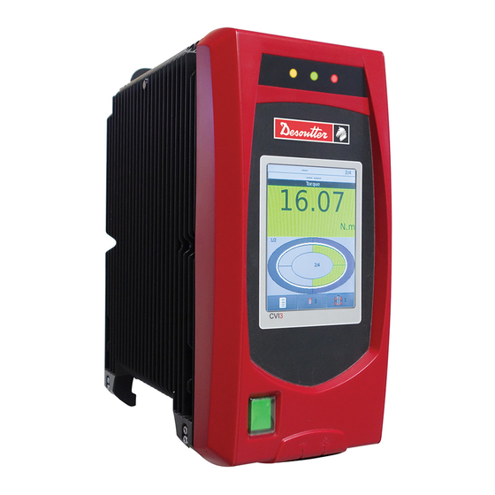
CVI3 Tightening Controllers
Installation and Upgrade Manual
Model
CVI3 Essential
CVI3 Function
CVI3 Function eSTOP
CVI3 Vision
CVI3 Vision eSTOP
TWINCVI3
TWINCVI3 eSTOP
Read all safety warnings and instructions
Failure to follow the safety warnings and instructions may result in
electric shock, fire and/or serious injury.
Save all warnings and instructions for future reference
WARNING
Printed Matter No.
Issue No.
Date
Part number
6159326950
6159326900
6159326930
6159326910
6159326940
6159326970
6159326980
www.desouttertools.com
6159924330_EN
04
08/2020
Advertisement
Table of Contents

Subscribe to Our Youtube Channel
Related Manuals for Desoutter CVI3 Series


Summary of Contents for Desoutter CVI3 Series
- Page 1 Printed Matter No. 6159924330_EN Issue No. Date 08/2020 CVI3 Tightening Controllers Installation and Upgrade Manual Model Part number CVI3 Essential 6159326950 CVI3 Function 6159326900 CVI3 Function eSTOP 6159326930 CVI3 Vision 6159326910 CVI3 Vision eSTOP 6159326940 TWINCVI3 6159326970 TWINCVI3 eSTOP 6159326980 WARNING Read all safety warnings and instructions Failure to follow the safety warnings and instructions may result in...
-
Page 2: Table Of Contents
Table of Contents Introduction............................ 4 Description ............................ 4 Controllers.......................... 4 List of compatible tightening tools .................. 4 Optional accessories...................... 4 eSTOP controllers........................ 4 ePOD ........................... 5 eBUS accessories........................ 6 Fieldbus modules ......................... 6 WIFI Access point ........................ 6 CVI CONFIG ........................ 7 CVIMONITOR ........................ 7 About Installation and Upgrade manual .................. 7 Warranty............................ 7 Installation restrictions ......................... 9 Checking the line voltage ........................ 9 Earthing the controller ........................ 9... - Page 3 Hardware upgrade .......................... 55 Upgrading CVI3 controllers ...................... 55 Checking the firmware version with CVIMONITOR ............ 55 Upgrading the firmware...................... 55 Software upgrade .......................... 56 Upgrading software ........................ 56 6159924330 - 08/2020 - 3 -...
-
Page 4: Introduction
8.20 6159170610 List of compatible tightening tools Most of Desoutter electric tools can be connected to CVI3 controllers. - CVI II tools range (by using the CVI II adaptor) - ERP nutrunners (by using the CVI II adaptor) - ERS screwdrivers (by using the ERS / ERPHT adaptor) - ERP high torque nutrunners are intended to be connected to CVI3 Essential / CVI3 Function / CVI3 Vision con- troller (by using the ERS / ERPHT adaptor). -
Page 5: Epod
• Advanced features such as advanced tightening strategies (seating detection and zero torque angle), the man- agement of positioning arms without any extra device. • Desoutter protocol. • CVILOGIX (Embedded PLC of CVI3 controllers). • ePOD2 eCompass enables to activate eCompass support for EAD20-1300/EAD32-900/EAD50-900/EAD70-800. -
Page 6: Ebus Accessories
IO expander 6159360740 Desoutter range of TRA and D53 positioning arms can be connected to the eBUS port of systems. CVI CONFIG wizard will help to calculate all data needed to correctly position the arm in the tightening area. The Learning mode feature included in the system will help you to determine precisely the tightening positions. -
Page 7: Cvi Config
There are no instructions in this manual about how to install a WI-FI access point. If you are not familiar with this type of installation, we recommend you to contact your Desoutter representative. CVI CONFIG CVI CONFIG is designed to set your systems point to point or via network with an intuitive and guided interface. - Page 8 • Damage to parts that occurs as a result of inadequate maintenance or performed by parties other than Desoutter or their Certified Service Partners during the warranty period is not covered by the warranty. • To avoid damage or destruction of tool parts, service the tool according to the recommended maintenance sched- ules and follow the correct instructions.
-
Page 9: Installation Restrictions
Installation restrictions Checking the line voltage Before connecting the controllers to the main supply, check that the line voltage is appropriate. Line voltage (V) 100-120 / 200-240 V~ The symbol ~ means "alternating current". Note that controllers can support 100-240 V~ single phase. However, the system works correctly at 100-120V or 200-240V~. -
Page 10: Hardware Installation
Hardware installation Installing controllers, tools and accessories Technical data Environment restrictions Refer to the Safety Instructions booklet supplied in the packaging box of controllers. Line protection Controllers have a JVL6-32 residual current circuit breaker with over-current protection which provides protection against earth leakage faults (30mA), overloads, short-circuits and over-current in the installation. - Page 11 CVI3 Essential 1 A (24V) CVI3 Function 1 A (24V) CVI3 Vision 1 A (24V) TWINCVI3 2 A (24V) Power supply 50/60 Hz Single-phase eBUS accessories power consumption 24V-1A maximum is supplied from the controller to power eBUS accessories and I/O connectors. We recommend to use an external power supply box to power all eBUS accessories connected.
- Page 12 S = apparent power measured in VA. P = true power measured in Watts. Q = reactive power measured in VAR. α = impedance phase angle. where T is the period of the signal. In a CVI3 controller, the power peak is 5kW. To dimension an installation, the apparent power consumption (S) is the only needed information.
-
Page 13: Recommended Installation Order
Controller Weight (kg) Weight (lb) CVI3 Vision 20.5 CVI3 Vision eSTOP 20.5 TWINCVI3 33.1 TWINCVI3 eSTOP 33.1 Recommended installation order Respect the following order. Install the controller. Connect the quick-stop if required. Connect the eSTOP controllers to a safety relay if required. Install and connect tools. - Page 14 Bottom panel USB port Auto-sensing input voltage mains connector Ground Fault Interruptor: earth fault and overcurrent protection Tool connector Ethernet port ePOD 2 USB ports - 14 - 6159924330 - 08/2020...
- Page 15 2 x 8 Input/Output connector Fieldbus slot eBUS RS232 port (2 serial ports) 4 Ethernet ports Dimensions Refer to the CAD 3D models and 2D views available at https://www.desouttertools.com/resource-centre. Mounting of controllers WARNING Electrical Hazard Risk of electrick shock. Place the controller in such a way the blue Ground Fault Interruptor located on the controller bottom panel ►...
- Page 16 Installing the table mounting kit See the drilling template delivered in the kit box. - 16 - 6159924330 - 08/2020...
- Page 17 Installing the wall mounting kit How to install a quick-stop system On delivery, I/O connectors are mounted in the controller and a shunt has been wired as shown. This means that the controller is continuously powered. 6159924330 - 08/2020 - 17 -...
- Page 18 If you require a quick-stop system, replace the existing shunt by the quick-stop wiring as shown below. Before removing the I/O connectors, switch off the GFI blue interruptor located on the bottom panel. Place the I/O connectors back in the controller as shown below. eSTOP controllers cables Always make sure to use the cables supplied with the controller.
- Page 19 Description Length (m) Length (ft) Part number Cable - 2 M8 male plugs 1.64 6159176260 Cable - 2 M8 male plugs 3.28 6159176330 Cable - 2 M8 male plugs 6.56 6159176340 Cable - 2 M8 male plugs 16.40 6159176350 Terminal plugs kit 6159176075 eSTOP controllers connection Bottom panel of eSTOP controllers...
- Page 20 Connect the terminal plug of the same color (supplied with the controller) when the connector is not used. CVI3 Function / CVI3 Vision - Tool stop Cable - 1 M8 male plug TWINCVI3 - Stop of both tools at the same time Cable - 1 M8 male plug Cable - 2 M8 male plugs TWINCVI3 - Stop of each tool separately...
- Page 21 Cable - 1 M8 male plug Cable - 1 M8 male plug How to connect the eSTOP plug to a safety relay Cable - 1 M8 male plug brown white blue black grey pink Emergency stop, light curtain and RESET connection - category 1 - Level C Reset Emergency stop brown...
- Page 22 white blue black grey pink Value for Value for Safety-related characteristic data 1 controller 2 controllers PL in accordance with EN ISO PL c PL c 13849-1:2015 Category in accordance with EN Cat. 1 Cat. 1 13849-1:2015 PFH in accordance with EN ISO 1.11E-07 1.80E-07 13849-1:2015 (test every year)
- Page 23 Value for Value for Safety-related characteristic data 1 controller 2 controllers MTTFd [hours] in accordance with EN HIGH – 93 years HIGH – 93 years ISO 13849-1:2015 TM in accordance with EN ISO 20 years 20 years 13849-1:2015 Input/Output connection Description AGND AGND...
- Page 24 Example of tightening process through IO flowchart Input/Output defined by default can be used to control the tightening process from a PLC or any other electronic de- vice. Here is an example of a standard exchange between a CVI3 controller and a PLC. - 24 - 6159924330 - 08/2020...
- Page 25 Example of tightening process through IO timing chart “Reset” signal is sent by the PLC. This leads to reset the report (“Tightening OK/NOK”). The controller receives the selection of Pset 1. The command is acknowledged by “Pset Selected” signal. The controller detects the “Start/Stop Tightening On State” signal transition. The tightening operation starts and “Tightening Running”...
-
Page 26: Connecting Cord Tools
Controller 1 Controller 2 Controller 3 Input Output Input Output Input Output +24V +24V +24V +24V +24V +24V Stop 1 Stop 1 COM1 Stop 1 COM1 COM1 COM1 COM1 Stop 2 Stop 2 Stop 2 Synchro Synchro Synchro Synchro Synchro Synchro 1N4148 1N4148... - Page 27 Connect the cable to the tool. Plug the cable with help of TOP indication. Tighten the nut. No need to tighten it too much. The locking system will prevent any loosening. To enable the loosening of the cable, actuate the locking trigger at the bottom of the handle. Connect the cable to the controller.
- Page 28 Do not set up the tool cable as shown below. Tool connector wiring diagram 0.25mm²/120Ω 0.25mm²/120Ω +15V 0.35mm² 0.35mm² Ground 1mm² or 2.5mm² 1mm² 1mm² 1mm² or 2.5mm² Phase 1 1mm² or 2.5mm² Phase 2 1mm² or 2.5mm² Phase 3 - 28 - 6159924330 - 08/2020...
-
Page 29: Connecting Cordless Tools To Cvi3 Vision
There are 2 typical configurations: • You have just received new Desoutter products (CVI3 Vision, cordless tool and WI-FI access point) and you want to create a basic workstation. The only thing to do is to declare the cordless tool in the controller by creat- ing a new tightening unit. - Page 30 Connect the WI-FI access point to any Ethernet port of the controller bottom panel. Plug a full-loaded battery pack to the cordless tool. Declare the cordless tool into CVI3 Vision controller. When the connection is done, the top left icon on the tool display is green and steady. P 0 0 0 To o l L o c k e d Declaring a cordless tool in CVI3 Vision controller...
- Page 31 Click this icon. Click this icon to display the current parameters of the tool. Change the parameters. Check that IP address, subnet mask and port number of the controller are correct. Click this icon to write the new parameters into the tool. The tool display shows Boot loader written in blue.
-
Page 32: Installing Ebus Accessories
Connect the access point to the same Ethernet network as the controller. Check that firmware versions of both tool and controllers are the most recent. If not, contact your Desoutter representative. Check that subnet masks are correct in the controller, tool and WI-FI access point. - Page 33 Mounting eBUS accessories Checking the contents of boxes Socket tray Termination plug SubD 9-pt Socket tray 4 screws M5x20 4 washers Bit tray Termination plug SubD 9-pt Bit tray Stacklight Stacklight 2 DIN Rail holders + 4 screws Termination plug SubD 9 pt 6159924330 - 08/2020 - 33 -...
- Page 34 2 mounting plates 2 screws M4x10 Keys Operator panel Operator panel Termination plug SubD 9-pt Support rails DIN TSH 35-2 Mounting plate accessories 2 screws M4x10 I/O expander I/O expander Cable entry system Termination grommet Ø 0 Connector 12-pt - pitch 3.81 Connector 10-pt - pitch 3.81 Connector 2-pt - pitch 3.81 Grommet Ø...
- Page 35 2 holders for DIN rail + 4 screws Screw M4x10 Mounting plate Wall mounting Any eBUS accessory can be mounted on a wall. See example below. For details, refer to the dimensional drawings. Secure the accessory by using M6 screws (not supplied). Table mounting Socket trays and bit trays can be mounted on a table.
- Page 36 Mounting on aluminium profile Stacklight, operator panel, IO expander For details, refer to the dimensional drawings. Position the mounting plates as shown below by using the screws supplied in the kit. Mount the accessory on the aluminium profile. For example Positioning the accessory on the eBUS network Use the encoding wheel of the accessory to select the position of the accessory on the eBUS cable.
- Page 37 Stacklight (position by default) IO expander (position by default) Operator panel (position by default) Remove the front panel to access the encoding wheel Encoding wheel This switch is set to 0. Do not change this setting. Installing sockets of the socket tray Internal centering 6159924330 - 08/2020 - 37 -...
- Page 38 0.35 Nm Pawn Ø ≤ socket M size Ø. Select the pawn and secure it by using the screw mounted on the socket tray. External guiding Socket outer Ø ≤ tube Ø. Tube no. Tube inner Ø (mm) If the socket is too short, cut the tubes. If the socket is too long, screw two or more similar tubes together as shown below.
- Page 39 Socket Locking part Select the tube, slide the locking part to block it and tighten with the knurled knob or the screw+washer provided in the packing box. Installing the bit module Select a bit in the following range: HEX: 4 to 8 TORX: 25 to 40 Remove the V-shaped part.
- Page 40 Bit hole Screw Insert the bit in the hole. Turn the screw clockwise for a heavier bit and counter-clockwise for a lighter bit. Customizing the order of the stacklight LEDs Colors by default are as follows. Orange Green Blue To change the order, remove each LED by unscrewing a 1/4 turn right. Reassemble the LEDs in the desired order.
- Page 41 Remove the front and the right side panels by unscrewing the screws. Wire and connect all connectors. Pass the cables through the corresponding grommets. Insert grommets Ø 0 when free space in order to ensure tightness. Fit the cable entry sytem to the I/O expander by using the 4 screws M5x15 supplied in the kit. The label marked 1 corresponds to the upper row of connectors.
- Page 42 eBUS cable connection and termination plug Plug the eBUS cable to the accessory. Put the termination plug into place as shown below when the accessory is unique on the eBUS network or when the accessory is the last one. Socket tray Bit tray Stacklight Operator panel...
-
Page 43: Installing An Epod
TRA and D53 positioning arms Check that the eBUS cable is connected from the encoder M12 or T-junction in case of 2 encoders. Connect an ePOD2 or above to the controller. Ensure you have a tape meter and a protractor close at hand to measure the characteristics of your installation. To get more information, refer to the user manuals of the positioning arms at https://www.desouttertools.com/ resource-centre. -
Page 44: Installing A Fieldbus Module
Installing a Fieldbus module Be aware that errors of manipulation can cause connection problems or a deterioration of electrical contacts. We strongly recommend that a technician from Desoutter installs the modules. Contact your Desoutter representative for support. Power off the system. -
Page 45: Connecting The Controller To The Power Supply
As there is only one physical RS232 connector on the controller bottom panel, use the Y cable (part number 6159176200) to use serial ports 1 and 2. Do not configure serial port 2 if the cable is not used. RS232 connector wiring diagram Connecting the controller to the power supply Use only the following power cords. -
Page 46: Powering On/Off The Controller
Powering ON/OFF the controller Push the GFI yellow button located on the bottom panel to check the earthing of the controller has been cor- rectly done. The controller should turn off. Switch on the GFI blue interruptor. On the front panel, press the on/off switch to power the controller on. On the front panel, press the on/off switch to power the controller off. -
Page 47: How To Set Up Networks
How to set up networks Overview about networks Desoutter Ethernet 1 is typically the wired network dedicated to production lines. Desoutter Ethernet 2 is typically the wired network dedicated to offices (company network). IP address by default Subnet mask by default System connected to Ethernet 1 192.168.5.x... - Page 48 Item Desoutter default parameter Other possible values Radio band 2.4 GHz - Channel 1-11 5 GHz - U-NII-1 5 GHz - U-NII-2 5 GHz - U-NII-2 ext 5 GHz - U-NII-3 Data rate 54 Mbit 1 Mbit 2 Mbit 5.5 Mbit...
-
Page 49: How To Connect A Cvi3 Controller To A Computer
Radio ETSI TELEC Channel band North America Europe Japan Worldwide U-NII-2 U-NII-2 Ext U-NII-3 How to ping an IP address This function is used to check the network connection with any device connected on the network. Select the IP address to ping. There are 4 attempts. For CVI3 Essential / CVI3 Function, go to Configuration >... - Page 50 The computer where CVI3 software is installed can be connected to the network via WI-FI or the Ethernet port 2 of any controller. Example of controllers connected to Ethernet networks - 50 - 6159924330 - 08/2020...
-
Page 51: Software Installation
150 Mo Monitor resolution 1280 x 1024 Installing CVI CONFIG Contact your Desoutter representative to get the last release of the software. Unzip the file and run the .exe file. The following start screen is displayed. 6159924330 - 08/2020 - 51 -... -
Page 52: Test And Validate Installation
Test and validate installation Testing and validating The goal is to have a cord tool and a cordless tool running a simple tightening process named "Pset". In our example, a cord tool and a cordless tool are connected to a CVI3 Vision controller. CVI CONFIG software is installed on the computer. -
Page 53: Creating A Pset In Cvi Config
Creating a Pset in CVI CONFIG Launch CVI CONFIG from the launchbar on the computer desktop. Click the icon Scan. In the column Action, click Add to a working area. In the next screen, click OK and click Exit when the transfer is done. See that the controller has been added in the working area. - Page 54 - 54 - 6159924330 - 08/2020...
- Page 55 Click this icon to display information about the system. Upgrading the firmware Contact your Desoutter representative to get the last version of firmware. On receipt of the .zip file, copy the content to a USB key. Unzip the file and copy/paste ".cvi3" and ".cvi3md5" files on the root of the USB key.
- Page 56 Go to the folder "Downloads" of your computer, copy the file and paste it in a safe location. Unzip the file and run the program. Contact your Desoutter representative to get more information and support. - 56 - 6159924330 - 08/2020...
- Page 60 Founded in 1914 and headquartered in France, Desoutter Industrial Tools is a global leader in electric and pneumatic assembly tools serving a wide range of assembly and manufacturing operations, including Aerospace, Automotive, Light and Heavy Vehicles, Off-Road, General Industry. Desoutter offers a comprehensive range of Solutions -tools, service and projects- to meet the specific demands of local and global customers in over 170 countries.
Need help?
Do you have a question about the CVI3 Series and is the answer not in the manual?
Questions and answers