Advertisement
Quick Links
ATAD-P0220-00 第7版/7th edition
取扱説明書 / INSTRUCTION MANUAL
手動圧着工具名/Manual crimping tool name
製品コード/Product code
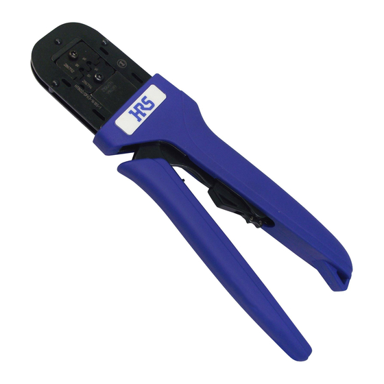
1. 工具の外観および各部の名称 / Configuration of the tool
ロットNo.表示/Lot number
番線表示/AWG number
クリンパ
/Crimper
アンビル/Anvil
端子ホルダー/
Contact holder
2. 圧着条件および圧着品質基準表 / Table of crimping conditions and crimping quality standard
STYLE
AWG
適合端子
No.
Applicable
contact No.
DF11-22SC
UL1061
DF11-22SCA
DF51K-22SC
DF51K-22SCA
電線ストリップ寸法 / Stripping dimension of wire
※ 圧着品質基準の詳細は、弊社の「圧着品質基準書ATAD-H0773-00, TAD-H-0131, TAD-H-0132」をご参照ください。
*
For further details of crimping quality standard, refer to 'Crimping quality standard manual ATAD-H0773-00, TAD-H-0131, TAD-H-0132'
of our company.
3. 作業手順 / Operating procedures
突き当て/
To be in contact
端子/Contact
3) Press the top end of the cable that has been stripped to a given length against the terminal holder, taking care not to allow its core wire to ravel.
For certain cases and for certain types of hand tools the tip of the terminal and the cable will have to be matched by eyesight, and the tip of the wire
will not touch the contact holder.
4) Compress the handle until the rachet releases and is open.
5) Withdraw the terminated wire from the tool, holding it by the wire. Exercise caution not to catch the contact in any part of the tool while doing it.
6) Make sure that it is properly crimped. (Refer to "Crimping conditions table and Crimping quality standard manual".)
[Caution]
When inserting the contact into the tool or taking it out from the tool be careful that the contact is not caught with the crimper, anvil,
etc., and is not deformed.
製造年月日表示/Date of manufacture
製品名表示/Tool number
HRSマーク表示/HRS logo
標準適合電線/Standard applicable wire
芯線構成
被覆外径
No.
Structure
Outside
of the
diameter
conductor
of the
Conductor
outer
insulation
22
17/φ0.16
φ1.3
0.64~0.70 1.50~1.65
ケーブル/Cable
HT801/DF11-22S(A)
CL550-0407-5
このダイヤルは工具組立時に調整するものでお客様のご使用時には使いません。/
This dial is not intended to be used by the customer during use, but to be adjusted at
the time of assembling the tool.
クリンプハイト
引張強度
Crimp height
(N)以上
Pull force
芯線
被覆
Outer
(N) or
more
insulation
52.92
1.7~2.3
1)
ハンドルを最後まで握りラチェットを解除させ、ハンドルを最大に開いてください。
2)
端子ホルダーのストッパーに突き当たる位置まで圧着バラ端子を挿入してくださ
い。
3)
所定の長さにストリップしたケーブル先端を、芯線がほつれないように端子ホル
ダーに突き当ててください。
ハンドツールの機種によっては、ケーブル先端を端子ホルダーに突き当てせず、
目視にて端子とケーブルの先端位置を合わせていただく場合があります。
4)
ハンドルをラチェットが解除するまで握って、ハンドルを開いてください。
5)
圧着された端子を電線を持って引き出してください。
6)
正規に圧着されているか確認してください。(「圧着条件表および圧着品質基準書」
をご参照ください。)
【注意】
端子を工具に挿入したり取り出す際、クリンパやアンビルに引っ掛ける
等で、端子を変形させないように注意してください。
1) Compress the handle until the moving handle releases and is fully open.
2)
Insert separated crimp terminal until it reaches the position at which it is pressed
against the terminal holder stopper.
ラチェット解除レバー/Rachet cancel lever
可動ハンドル/Moving handle
圧着品質基準 / Crimping quality standard
項目
寸法
Item
Dimension
被覆位置
芯線先端位置
Outer
Protrusion of
0.2~0.7
insulation
the conductor
position
ベルマウス
ローリング
0.1~0.2
Bell mouth
Rolling
ベントアップ
ランス高さ
2°MAX
Bent UP
Lance hight
ベントダウン
バリ高さ
3°MAX
Bent DOWN
Burr hight
ツイスト
ギャップ寸法
±2°MAX
Twist
Gap dimension
項目
寸法
Item
Dimension
0.2~0.5
±5°MAX
1.8~1.9(DF11)
2.05~2.1(DF51K)
0.1MAX
-
Advertisement

Subscribe to Our Youtube Channel
Related Manuals for HRS HT801/DF11-22S


Summary of Contents for HRS HT801/DF11-22S
- Page 1 ATAD-P0220-00 第7版/7th edition 取扱説明書 / INSTRUCTION MANUAL 手動圧着工具名/Manual crimping tool name HT801/DF11-22S(A) 製品コード/Product code CL550-0407-5 1. 工具の外観および各部の名称 / Configuration of the tool このダイヤルは工具組立時に調整するものでお客様のご使用時には使いません。/ This dial is not intended to be used by the customer during use, but to be adjusted at ロットNo.表示/Lot number...
- Page 2 4. 使用上の注意 / Handling precautions 手動圧着工具は、クリンプハイトの微調整が行えませんので、端子の適合電線範囲 であっても、ご使用になる電線が指定電線と異なる場合は、工具に適合しない場合 があります。 適合端子,適合ケーブル以外の物を、絶対に圧着しないでください。 工具を叩いたり、高い所から落とす等の衝撃は、絶対加えないでください。 工具には適正な加圧が行われるまでハンドルが開かないように、ラチェット機構が 備わっています。トラブル等により圧着作業の途中でハンドルを開く場合は、ラチェッ ト解除レバーにてラチェットを解除してください。ラチェット解除レバーを使用しないで ラチェット解除レバー/ 無理に開いたりすると、工具が故障しますので絶対にしないでください。 Ratchet cancel lever クリンパとアンビルがダイスタッチした後もハンドルに過度な荷重をかけ続けますと、 圧着工具のガタを引き起こし正常な圧力が得られなくなる原因になりますのでご注 意ください。 作業を始める時は、圧着した端子の圧着状態が良品の範囲になっているか確認を 行ってください。 本工具には安全カバー等の安全装置は取り付いていません。圧着作業に際して は、ハンドル部に指等挟まないよう安全に十分配慮してご使用ください。 工具には改造等を加えないでください。 工具の使用期間中は、定期的に清掃を行ってください。 【注意】 工具の外観・形状は予告なく変更することがあります。 The tools can not be adjusted for crimp height or configuration. Only specified wire size, construction and type must be used with the applicable contact and tool.
Need help?
Do you have a question about the HT801/DF11-22S and is the answer not in the manual?
Questions and answers