
Related Manuals for Kongsberg K-Sync V1


Summary of Contents for Kongsberg K-Sync V1
- Page 1 PUBLIC KONGSBERG K-Sync Synchronization system Installation manual 342741/C February 2023 © Kongsberg Maritime AS...
- Page 2 Kongsberg Maritime disclaims any responsibility for damage or injury caused by improper installation, use or maintenance of the equipment. Disclaimer Kongsberg Maritime AS endeavours to ensure that all information in this document is correct and fairly stated, but does not accept liability for any errors or omissions. Support information If you require maintenance or repair, contact Kongsberg Maritime’s support organisation.
-
Page 3: Table Of Contents
Installation manual Table of contents ABOUT THIS MANUAL ..............5 KONGSBERG K-SYNC ..............6 System description ........................7 System diagram........................9 Concept description ......................10 Main system units ........................11 Synchronization Unit description .................11 Computer description ....................11 Scope of supply........................12 Network security........................ - Page 4 KONGSBERG K-Sync Cable plan ..........................43 List of cables ......................... 44 Echo sounder trigger interface overview ................45 Determine which signals need to be interfaced and their characteristics ......47 Signal interface overview .................... 48 Techniques for determine signal properties ................49 I/O module, adjusting ......................
-
Page 5: About This Manual
We assume that you are familiar with the basic acoustic principles of sound in water. Online information For information about the K-Sync and other products from Kongsberg Maritime, see the KONGSBERG website: •... -
Page 6: Kongsberg K-Sync
KONGSBERG K-Sync Installation manual KONGSBERG K-Sync Topics System description, page 7 System diagram, page 9 Concept description, page 10 Main system units, page 11 Scope of supply, page 12 Network security, page 13 Support information, page 14 342741/C... -
Page 7: System Description
KONGSBERG K-Sync System description The K-Sync is a compact synchronization system designed to support all types of echo sounders, sonars and other hydroacoustic instruments provided with an external transmission trigger option. The K-Sync Synchronization Unit can control up to 16 hydroacoustic systems. - Page 8 KONGSBERG K-Sync Installation manual The computer running the K-Sync application software needs to interface the Synchronization Unit for the system to initialize. This interface is made using an Ethernet line. Once the K-Sync system is running, the application software can be closed, and the computer disconnected from the Synchronization Unit.
-
Page 9: System Diagram
Unless otherwise specified in a contract, the computer and the display are not included in the standard delivery from Kongsberg Maritime. These are commercial items that can be purchased locally. A laptop computer can be used if it meets the technical requirements. -
Page 10: Concept Description
KONGSBERG K-Sync Installation manual Concept description The K-Sync synchronization system offers a highly adjustable timing of transmissions (pinging) when multiple echo sounders, sonars or other hydroacoustic instruments are employed on a vessel. The K-Sync synchronization system controls and optimizes the timing for each transmission from each hydroacoustic system. -
Page 11: Main System Units
Unless otherwise specified in a contract, the computer and the display are not included in the standard delivery from Kongsberg Maritime. These are commercial items that can be purchased locally. A laptop computer can be used if it meets the technical requirements. -
Page 12: Scope Of Supply
The main units you need are provided with the standard delivery. Note Spare parts and additional services provided by Kongsberg Maritime are not listed. For a list of spare parts and services, refer to the contract and/or the order confirmation. -
Page 13: Network Security
The damage done if a remote computer succeeds doing this. Kongsberg Maritime has no information regarding the complete system installation on any vessel. Systems provided by Kongsberg Maritime are regarded as stand-alone offline systems. They are stand-alone even though they may be connected to a network for sensor interfaces and/or data distribution. -
Page 14: Support Information
Support information Should you need technical support for your K-Sync system you must contact a Kongsberg Maritime office. A list of all our offices is available on our website. You can also contact our main support office in Norway. - Page 15 KONGSBERG K-Sync • : Strandpromenaden 50, 3183 Horten, Norway Address • https://www.kongsberg.com/maritime/ Website • km.hydrographic.support@kongsberg.com Email address KM Support is also available in the KM-App. The KM-Support App is available for free in the App Store and Google Play. The use of the KM-Support App is free of charge.
-
Page 16: Preparations
KONGSBERG K-Sync Installation manual Preparations Topics Tools, equipment and consumables required for installation, page 16 Personnel qualifications, page 17 Tools, equipment and consumables required for installation To install the K-Sync system, all necessary tools and equipment for mechanical work, cabinet installation and electrical wiring must be available. -
Page 17: Personnel Qualifications
Preparations Personnel qualifications The installation of the K-Sync system is a demanding task. Electrical connections can only be made by skilled personnel (ship electricians, technicians or engineers). As a minimum, a technician trained for or experienced with electronic or electric installation work. -
Page 18: Installing The Software
KONGSBERG K-Sync Installation manual Installing the software Topics Read this first, page 19 Installing the K-Sync application software, page 20 Configuring the network address - Synchronization Unit V1, page 21 Configuring the network address - Synchronization Unit V2, page 23... -
Page 19: Read This First
Installing the software Read this first Caution Always power up the Synchronization Unit before other echo sounders are turned on to avoid accidental pinging. Trigger outputs are undefined during power-up (first 20 seconds) and signal levels could potentially be interpreted as trigger pulse by the echo sounders until signal levels have settled. -
Page 20: Installing The K-Sync Application Software
KONGSBERG K-Sync Installation manual Installing the K-Sync application software Set up of Workstation includes configuration of the network card and installing the K-Sync application software. Prerequisites The Workstation must be set up with an address in the 157.237.60.xxx (255.255.240.0) subnet. -
Page 21: Configuring The Network Address - Synchronization Unit V1
If you can’t contact the Synchronization Unit you may have to change the IP address of your local computer to 157.237.60.160 Procedure Close K-Sync Application, if running. Via Windows Start menu navigate to , click Kongsberg Maritime Upgrade Synchronization Unit When the has started, click under Upgrade Unit application... - Page 22 KONGSBERG K-Sync Installation manual 11 Open the K-Sync Application and reconfigure the K-Sync Application System Settings Open K-Sync Application Select Settings System Settings Configure the Synchronization Unit IP address to match the new IP address of theSynchronization Unit. 342741/C...
-
Page 23: Configuring The Network Address - Synchronization Unit V2
Installing the software Configuring the network address - Synchronization Unit V2 Description on how to change the network address of the Synchronization Unit. Prerequisites • This procedure assumes that the subnet for the network interface is the same as the existing configuration of the Synchronization Unit (otherwise you will not be able to connect to it). - Page 24 KONGSBERG K-Sync Installation manual Result When you open the K-Sync application it should start working with the new configuration. 342741/C...
-
Page 25: Installing The Synchronization Unit
Installing the Synchronization Unit Installing the Synchronization Unit Topics Synchronization Unit description for installation, page 26 Installing the rack mounted version, page 27 Installing the cabinet version, page 30 Syncronization Unit V1 main parts, page 31 Syncronization Unit V2 main parts, page 32 342741/C... -
Page 26: Synchronization Unit Description For Installation
KONGSBERG K-Sync Installation manual Synchronization Unit description for installation The Synchronization Unit consists of a programmable logic controller (PLC) and other electronic circuitry that provide the synchronized trigger signals. The Synchronization Unit is available in two different versions, based on different versions of the programmable logic controller (PLC) inside. -
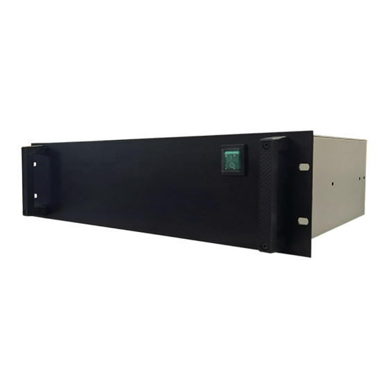
Page 27: Installing The Rack Mounted Version
Installing the Synchronization Unit Installing the rack mounted version The Synchronization Unit is designed to be mounted in a 19-inch rack. Prerequisites You must be equipped with a standard set of tools. This tool set must comprise the normal tools for electronic and electromechanical tasks. This includes different screwdriver types, pliers, spanners, a cable stripper, a soldering iron, etc. - Page 28 KONGSBERG K-Sync Installation manual Version 1 (V1) Unscrew four screws ( ) on each side of the rack unit. Unscrew four thumb screws ( ) in front Unscrew three screws ( ) on the back side of the rack unit.
- Page 29 Installing the Synchronization Unit Lift the top cover off the rack unit. Result The unit is now ready for connection of the cables. Related topics 324131 Synchronization Unit dimensions (19" rack version) - V1, page 87 110-0010683 Synchronization Unit dimensions (19" rack version) - V2, page 89 Installing the K-Sync cables, page 55 342741/C...
-
Page 30: Installing The Cabinet Version
KONGSBERG K-Sync Installation manual Installing the cabinet version The cabinet is designed for installation in a technical room or a sheltered environment. Make sure that the location offers ample space around the cabinet to allow for cables, maintenance and parts replacement. -
Page 31: Syncronization Unit V1 Main Parts
Installing the Synchronization Unit Syncronization Unit V1 main parts The main parts of the Synchronization Unit include three power supplies, the programmable logic controller (PLC) with its associated devices, as well as the terminal board. Power supply module (+5 VDC) Power supply module (+12 VDC) PLC (Programmable logic controller) Circuit breaker... -
Page 32: Syncronization Unit V2 Main Parts
KONGSBERG K-Sync Installation manual Syncronization Unit V2 main parts The main parts of the Synchronization Unit include three power supplies, the programmable logic controller (PLC) with its associated devices, as well as the terminal board. Circuit breaker (24 VDC input) - Page 33 Installing the Synchronization Unit Digital I/O module (PLC) I/O module 1 I/O module 2 I/O module 3 I/O module 4 Solid-state relay module 342741/C...
-
Page 34: Echo Sounder Signal Characteristics
KONGSBERG K-Sync Installation manual Echo Sounder Signal characteristics This chapter describes the definitions and characteristics of the signals that are used in the K-Sync system. Topics Signal naming conventions, page 35 K-Sync Signal Interface, page 35 Logic states and their corresponding voltage levels, page 37... -
Page 35: Signal Naming Conventions
K-Sync application. The second column shows the typical names used for the corresponding signal of the sonar. These are names used by the Kongsberg echo sounders Table 4 Signal naming convention... - Page 36 KONGSBERG K-Sync Installation manual Feedback signals from the echo sounder Feedback signals are not required but will be used when available. If feedback signals are not available, the Synchronization Unit can estimate the waiting period required for the echo sounder to become ready.
-
Page 37: Logic States And Their Corresponding Voltage Levels
Echo Sounder Signal characteristics Logic states and their corresponding voltage levels Note In this manual Signal active refers to a particular voltage level which is present for a specific state, but does not imply whether this voltage is negative, 0 or positive. Using this generic terminology avoids confusion. - Page 38 KONGSBERG K-Sync Installation manual – RS-232; if positive voltage (+3V to +12V) to negative voltage (-12V to -3V) causes transmit, then the trigger active level is high (trigger on rising edge). – TTL; if 0 to +5V causes transmit, then the trigger active level is high (trigger on rising edge).
-
Page 39: Signals Timing Specification
Supported signal levels (inputs and TTL and RS-232 TTL and RS-232 outputs) Supported depth datagram input • Kongsberg EM: D, X, and E • Kongsberg EM: D, X, and E • Kongsberg EA 500 • Kongsberg EA 500 • NMEA: DPT and DBS •... -
Page 40: I/O Module Configuration
KONGSBERG K-Sync Installation manual I/O module configuration The echo sounders can be connected to the I/O modules in any order. The modules configure how the voltage levels are to be interpreted; while the K-Sync Application handles the remaining signal properties and assignments. -
Page 41: Cable Layout And Interconnections
Cable layout and interconnections Cable layout and interconnections Topics Read this first, page 42 Cable plan, page 43 List of cables, page 44 Echo sounder trigger interface overview, page 45 Determine which signals need to be interfaced and their characteristics, page 47 Techniques for determine signal properties, page 49 I/O module, adjusting, page 52 Installing the K-Sync cables, page 55... -
Page 42: Read This First
Each drawing provides additional information, and may, when applicable, include minimum specifications, connector terminations and the required number of cores. Drawings are generally not provided for standard commercial cables. Cables fall into three categories. : System cables are provided by Kongsberg Maritime as a part of the System cables delivery. -
Page 43: Cable Plan
Cable layout and interconnections Cable plan The cable plans shows the Synchronization Unit with the computer and an optional Ethernet switch. Display Computer Ethernet switch (Optional) Synchronization Unit The Ethernet cable between the Synchronization Unit and the computer can either be connected directly between the two units, or via an Ethernet switch. -
Page 44: List Of Cables
KONGSBERG K-Sync Installation manual List of cables A set of cables is required to connect the Synchronization Unit to the power source and vessel ground. Additional cables are required to connect the Synchronization Unit to the echo sounders that need to be synchronized. -
Page 45: Echo Sounder Trigger Interface Overview
Sensor triggers on logical high Select Active High Falling Edge Sensor triggers on logical low Select Active Low Rising Edge See table below to find which entry to select in the K-Sync Installation settings for different types of Kongsberg equipment. 342741/C... - Page 46 KONGSBERG K-Sync Installation manual Table 7 Trigger interface overview (KM) Inputs from echo sounder Trigger output to echo sounder Make and Pulse properties Ready to Transmitting - Signal setting - model transmit - Trigger Pulse length Signal Active Signal active...
-
Page 47: Determine Which Signals Need To Be Interfaced And Their Characteristics
Refer to Logic states and their corresponding voltage levels for definitions. A copy of the table below has been completed for the Kongsberg echo sounders. Refer Table 7 Trigger interface overview (KM), page 46 Keep a copy of the table with the final setup with the ship’s records for future reference. -
Page 48: Signal Interface Overview
KONGSBERG K-Sync Installation manual Signal interface overview Complete the table for syncronization setup configuration. The setting configuration is saved. A backup can be saved by File Backup config files Table 8 Signal interface table Inputs from echo sounder Trigger output to echo sounder... -
Page 49: Techniques For Determine Signal Properties
Cable layout and interconnections Techniques for determine signal properties Note This step only needs to be performed for echo sounders where the signal properties are not fully specified. The signal characteristics of the trigger and the feedback signals can be determined manually if not known. - Page 50 KONGSBERG K-Sync Installation manual Signal LEDs on I/O modules LEDs on the I/O modules will be used for debugging in this section. There are 4 LEDs that indicate the signal level for trigger and feedback signals, and this is the location:...
- Page 51 Cable layout and interconnections If the echo sounder provides a transmitting signal (TRIG OUT) then this LED should change state at time of ping if signal has been connected. If the echo sounder pings → → when the trigger LED turns on, then set the Settings Installation Installation Settings...
-
Page 52: I/O Module, Adjusting
KONGSBERG K-Sync Installation manual Configure to use : Fixed period and set the Fixed period Runtime settings Trigger mode to 1000 ms. Observe the bottom-right of the four LEDs, the Transmitting (in). Observe that the Transmitting LED blinks each time the echo sounder is being triggered by the Synchronization Unit. - Page 53 Cable layout and interconnections The I/O module contains the following details: LED indicators for input/output channels Pull-down or pull-up resistance for TTL signals according to whether the signal is active high or low, Associated resistor value to be set according to your signal transmission conditions.
- Page 54 KONGSBERG K-Sync Installation manual 342741/C...
-
Page 55: Installing The K-Sync Cables
Cable layout and interconnections Installing the K-Sync cables Topics Connecting the Synchronization Unit to AC mains, ground and Ethernet - V1, page 56 Connecting the Synchronization Unit to DC mains, ground and Ethernet - V2, page 59 Connecing K-Sync I/O module to echo sounders, page 62 342741/C... -
Page 56: Connecting The Synchronization Unit To Ac Mains, Ground And Ethernet - V1
KONGSBERG K-Sync Installation manual Connecting the Synchronization Unit to AC mains, ground and Ethernet - V1 The Synchronization Unit V1 must be connected to AC mains, and it must be properly grounded. Prerequisites You must be equipped with a standard set of tools. This tool set must comprise the normal tools for electromechanical tasks. - Page 57 Cable layout and interconnections Figure 3 Rack mounted version connectors Connector for 110 to 240 Vac power cable Connector for RJ45 Ethernet cable 16 PG nipples for sealed signal cable gland Screw for connecting ground cable 342741/C...
- Page 58 KONGSBERG K-Sync Installation manual Observe the following connectors on the bottom side of the K-Sync cabinet: Figure 4 Cabinet version connectors 6 large PG nipples for sealed signal cable gland 9 small PG nipples for sealed signal cable gland Connector for 110 to 240 Vac power cable...
-
Page 59: Connecting The Synchronization Unit To Dc Mains, Ground And Ethernet - V2
Cable layout and interconnections Result The unit is now ready for connection of the signal cables. Related topics Cable plan, page 43 Connecing K-Sync I/O module to echo sounders, page 62 AC power cable using IEC C13 inline socket, page 66 Connecting the Synchronization Unit to DC mains, ground and Ethernet - V2 The Synchronization Unit V2 must be connected to DC mains, and it must be properly... - Page 60 KONGSBERG K-Sync Installation manual Screw for connecting ground cable Connector for RJ45 Ethernet cable Procedure Open the unit. Locate the terminals for DC connection. Insert the cable through one of the cable glands delivered with the unit. Connect the power cable from the Synchronization Unit to the DC power outlet. (C3) Locate the connection for the grounding.
- Page 61 Cable layout and interconnections Locate the Ethernet connector. (B) Connect the Ethernet cable from the Synchronization Unit to the Ethernet socket on the computer. (C8) If the length of the Ethernet cable exceeds approximately 60 metres, it is recommended to use an Ethernet switch to maintain the signal strength. If the optional Ethernet switch is used, make the Ethernet connection between the Synchronization Unit and the computer via this Ethernet switch.
-
Page 62: Connecing K-Sync I/O Module To Echo Sounders
KONGSBERG K-Sync Installation manual Connecing K-Sync I/O module to echo sounders 19" rack version 16 PG nipples for sealed cable gland 16 Digital numbered from I/O modules left to right when seen from rear side of the cabinet Cabinet version... - Page 63 Cable layout and interconnections I/O module The K-Sync cabinet holds up to 16 digital and 16 cable gland PG nipples, thus modules 16 systems can be synchronized using K-Sync. Each I/O module holds two 3 pin connectors with two termination blocks attached. The termination blocks can be disconnected for easy access to terminate the signal cables.
- Page 64 Prepare the appropriate signal cable from the echo sounder. Echo sounder trigger interface overview, page 45, for trigger signal specifications for the Kongsberg Maritime echo sounders. Enter the signal cable through the PG nipple at the back side of the cabinet. Note Remove the cable insulation from the termination block up to the PG nipple.
-
Page 65: Cable Drawings And Specifications
Cable layout and interconnections Cable drawings and specifications Topics AC power cable using IEC C13 inline socket, page 66 DC Power cable - V2, page 68 Ground cable, page 69 RJ45 High speed Ethernet cable (1000Base-t), page 70 K-Sync interface to EM Processing Unit, page 71 K-Sync interface to EA400 and EA600 interface, page 73 K-Sync interface to EA440 and EA640 interface, page 75 K-Sync interface to generic RS-232 synchronization input, page 77... -
Page 66: Ac Power Cable Using Iec C13 Inline Socket
KONGSBERG K-Sync Installation manual AC power cable using IEC C13 inline socket This cable is used to connect any unit or device to AC mains supply. The power cable is commercial. It is normally used for 115 and 230 VAC. The inline socket and the plug both comply to the IEC60320 standard. - Page 67 Cable layout and interconnections Note There are substantial differences between countries nomenclature related to power plugs and sockets. Observe local standards and regulations. Minimum cable requirements • : 2 x 1.5 mm + 1.5 mm Ground Conductors • : None Screen •...
-
Page 68: Dc Power Cable - V2
KONGSBERG K-Sync Installation manual DC Power cable - V2 DC mains is connected to the circuit breaker in the Synchronization Unit. Circuit breaker (24 VDC input) Make the connections here. X2.3 - Positive X2.4 - Negative A standard commercial power supply providing 24 VDC 6A can be used. -
Page 69: Ground Cable
Cable layout and interconnections Ground cable Correct grounding is essential for safe operation and maximum performance. Ground tag on unit Vessel ground The ground connection is made using a thick stranded (or braided) cable making a solid connection between the cabinet and the bulkhead. -
Page 70: Rj45 High Speed Ethernet Cable (1000Base-T)
KONGSBERG K-Sync Installation manual RJ45 High speed Ethernet cable (1000Base-t) Most high speed data connections between the K-Sync system units are made using Ethernet cables. These cables may also be used between the K-Sync and peripheral equipment. Local Ethernet connection... -
Page 71: K-Sync Interface To Em Processing Unit
Cable layout and interconnections K-Sync interface to EM Processing Unit This connection allows synchronisation of the following Kongsberg Maritime echo sounders: • EM 124 / EM 304 / EM 712 • EM 2040 The cable is not included with the delivery, and must be provided by the installation shipyard. - Page 72 KONGSBERG K-Sync Installation manual Cable specifications Cable requirements may vary depending on the specific sonar you interface. Please consult the installation manual of the equipment for specific cable requirements. 342741/C...
-
Page 73: K-Sync Interface To Ea400 And Ea600 Interface
Cable layout and interconnections K-Sync interface to EA400 and EA600 interface This connection allows synchronisation of the following Kongsberg Maritime echo sounders: • EA 400 / EA 600 The cable is not included with the delivery, and must be provided by the installation shipyard. - Page 74 KONGSBERG K-Sync Installation manual Trig out -> /RS232 <- Gnd <- Trig in / TTL <- Gnd Not used Cable specifications Cable requirements may vary depending on the specific sonar you interface. Please consult the installation manual of the equipment for specific cable requirements.
-
Page 75: K-Sync Interface To Ea440 And Ea640 Interface
Cable layout and interconnections K-Sync interface to EA440 and EA640 interface This connection allows synchronisation of the following Kongsberg Maritime echo sounders: • EA 440 / EA 640 The cable is not included with the delivery, and must be provided by the installation shipyard. - Page 76 KONGSBERG K-Sync Installation manual Cable specifications Cable requirements may vary depending on the specific sonar you interface. Please consult the installation manual of the equipment for specific cable requirements. 342741/C...
-
Page 77: K-Sync Interface To Generic Rs-232 Synchronization Input
Cable layout and interconnections K-Sync interface to generic RS-232 synchronization input For transmission synchronization purposes, the K-Sync will interface a generic RS-232 serial line communication port using the CTS (Clear To Send) and RTS (Request To Send) signals. The synchronized product is connected to the IO Module inside the K-Sync Synchronization Unit. - Page 78 KONGSBERG K-Sync Installation manual Connectors 1 through 6 as indicated by the arrows. Note that each of the two connector elements can be pulled out of the IO Module for easy access. Configuration board Unless otherwise specified, this cable must be provided by the installation shipyard.
-
Page 79: Cable Gland Procedure
Cable gland procedure Cable gland procedure Cable glands are used whenever a cable passes through a water-tight bulkhead or into a cabinet, to seal the opening through which the cable passes and to protect the cable from abrasion on the edges of the hole. Follow the guidelines detailed here when installing cables through cable glands. - Page 80 KONGSBERG K-Sync Installation manual Slacken and remove the compression nut from the cable gland, and extract the compression seal and the screen collar from the body of the gland. Depending on whether the cable has already been installed in conduits, either: •...
- Page 81 Cable gland procedure 13 Connect the cable cores to the appropriate terminals within the cabinet. Further requirements Use a blind plug to cover the points not in use. 342741/C...
-
Page 82: Configuration Of The K-Sync Application
KONGSBERG K-Sync Installation manual Configuration of the K-Sync application Configuration of K-Sync is described in K-Sync Operator Manual, reg.nr. 342435. 342741/C... -
Page 83: Technical Specifications
Technical specifications Technical specifications Topics Weights and outline dimensions, page 84 Power requirements, page 85 Environmental requirements, page 85 342741/C... -
Page 84: Weights And Outline Dimensions
KONGSBERG K-Sync Installation manual Weights and outline dimensions 19" rack version - V1 • : K-Sync (19" rack version) Make and model • Outline dimensions – : 177.25 mm (4U) Height – : 482 mm (19" rack) Width – : 400 mm (Approximately) Depth •... -
Page 85: Power Requirements
Technical specifications Power requirements 19" rack version / Cabinet version - V1 • : K-Sync Make and model • : 110 - 240 VAC Voltage requirement • : 80 W (Typical) Power consumption • : The use of uninterruptible power supply (UPS) is highly recommended Power interrupts 19"... -
Page 86: Drawing File
KONGSBERG K-Sync Installation manual Drawing file Topics 324131 Synchronization Unit dimensions (19" rack version) - V1, page 87 344459 Synchronization Unit dimensions (Cabinet version) - V1, page 88 110-0010683 Synchronization Unit dimensions (19" rack version) - V2, page 89 342741/C... -
Page 87: 324131 Synchronization Unit Dimensions (19" Rack Version) - V1
Drawing file 324131 Synchronization Unit dimensions (19" rack version) - V1 Contact our support organization to obtain the source file(s). 342741/C... -
Page 88: 344459 Synchronization Unit Dimensions (Cabinet Version) - V1
KONGSBERG K-Sync Installation manual 344459 Synchronization Unit dimensions (Cabinet version) - V1 Contact our support organization to obtain the source file(s). 342741/C... -
Page 89: 110-0010683 Synchronization Unit Dimensions (19" Rack Version) - V2
Drawing file 110-0010683 Synchronization Unit dimensions (19" rack version) - V2 342741/C... - Page 90 KONGSBERG K-Sync Installation manual Index 1000Base-T Ethernet cable ..........70 DC power cable connecting ..........59 connection ..........68 specification ..........68 about description target audience ..........5 commercial cables ........42 AC power computer ..........11 cable ............66 K-Sync .............
- Page 91 ....27 K-Sync concept description ........10 synchronization using RS-232 serial line..... 77 system description ........7 qualifications Kongsberg Maritime personnel ..........17 support ............ 14 Read this first line socket HW installation .......... 42 IEC............
- Page 92 KONGSBERG K-Sync Installation manual personnel qualifications ......... 17 RJ45 target audience Ethernet cable ..........70 this publication ..........5 RS-232 technical specifications synchronization .......... 77 environmental requirements......85 RTS (Request To Send) outline dimensions........84 synchronization .......... 77 power requirements........85 weight .............
- Page 94 ©2023 Kongsberg Maritime...
Need help?
Do you have a question about the K-Sync V1 and is the answer not in the manual?
Questions and answers