
Related Manuals for Kongsberg TTC Series


Summary of Contents for Kongsberg TTC Series
- Page 1 Instruction Manual Transponder test and configuration unit kongsberg.com 350839/D...
- Page 3 Transponder test and configuration unit Instruction Manual 350839/D February 2024 © Kongsberg Discovery AS...
- Page 4 Kongsberg Discovery disclaims any responsibility for damage or injury caused by improper installation, use or maintenance of the equipment. Disclaimer Kongsberg Discovery AS endeavours to ensure that all information in this document is correct and fairly stated, but does not accept liability for any errors or omissions. Support information If you require maintenance or repair, contact Kongsberg Discovery’s support...
-
Page 5: Table Of Contents
Instruction Manual Table of contents ABOUT THIS MANUAL .............. 5 TTC..................6 System description ......................7 Transponder test and configuration unit (TTC) ..............8 Support information ......................9 OPERATING PROCEDURES ............. 10 Opening and closing the case................... 11 Connecting to AC power and charging the unit’s battery..........12 Switching the unit on and off...................13 Standby mode ........................13 Doing an acoustic test ......................14... - Page 6 Weight and outline dimensions ..................36 DRAWING FILE..............37 TTC outline drawing......................38 Test transducer outline drawing ..................39 350839/D...
-
Page 7: About This Manual
Registered trademarks Observe the registered trademarks that apply. Windows ® is a registered trademark of Microsoft Corporation in the United States and other countries. cNODE ® is a registered trademark of Kongsberg Discovery AS in Norway and other countries. 350839/D... -
Page 8: Ttc
TTC Instruction Manual Topics System description, page 7 Transponder test and configuration unit (TTC), page 8 Support information, page 9 350839/D... -
Page 9: System Description
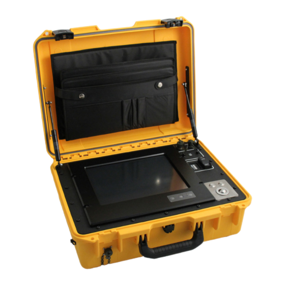
System description The transponder test and configuration unit is designed for on deck testing and configuration of transponders. The TTC unit can test all Kongsberg transponder channels, Cymbal and FSK. It can also test telemetry transponders with internal and external sensors. -
Page 10: Transponder Test And Configuration Unit (Ttc)
The power cable connects the TTC unit to a 110/230 VAC power supply. Only use the power cable supplied with the unit. Do not use if damaged or excessively worn. Contact Kongsberg for a replacement. Note Do not use the control panel as a storage space when the unit is not in use. Do not place the cable organizer bag and/or the cables on top of the touch screen and close the lid. -
Page 11: Support Information
Support information Should you need technical support for your TTC system you must contact a Kongsberg Discovery office. A list of all our offices is available on our website. You can also contact our main support office in Norway. Manuals and technical information can be downloaded from our support website. -
Page 12: Operating Procedures
TTC Instruction Manual Operating procedures Topics Opening and closing the case, page 11 Connecting to AC power and charging the unit’s battery, page 12 Switching the unit on and off, page 13 Standby mode, page 13 Doing an acoustic test, page 14 Configure or reconfigure a transponder, page 15 350839/D... -
Page 13: Opening And Closing The Case
Operating procedures Opening and closing the case The case latches are fitted with a safety mechanism preventing unintentional opening. Context Place the unit on a steady and level surface. Secure the unit to minimize the risk of harm to personnel and equipment. Procedure Opening the case. -
Page 14: Connecting To Ac Power And Charging The Unit's Battery
ON/OFF Context Only use the power cable supplied with the unit. Do not use if damaged or excessively worn. Contact Kongsberg for a replacement. Procedure Connect and secure the power cable to the unit’s power connector. The power connector is located below the left latch. -
Page 15: Switching The Unit On And Off
Operating procedures Switching the unit on and off switch is located on the right, labelled ON OFF. ON/OFF Context When switched on, the unit can either run on power from an external 110/230 VAC power supply or on power from the internal battery. It is not necessary to disconnect the unit from the external power supply during use. -
Page 16: Doing An Acoustic Test
TTC Instruction Manual Doing an acoustic test Before using the transponder, it is recommended that you do an acoustic test to ensure that the transponder is in full working order. Context Secure the transponder to minimize the risk of harm to personnel and equipment. The test transducer is for communication in air only so always set the TTC unit’s power level to either minimum or low prior to testing. -
Page 17: Configure Or Reconfigure A Transponder
Operating procedures Configure or reconfigure a transponder Follow this procedure if the transponder has to be configured or reconfigured. Context Secure the transponder to minimize the risk of harm to personnel and equipment. Procedure Open the case. Switch on the unit. Connect the serial line cable to the SERIAL port in the upper right corner and to the port... -
Page 18: Control Panel
TTC Instruction Manual Control panel Topics Control panel, page 17 Controls, page 17 Touch screen, page 18 Acoustic Test tab, page 18 Transponder Configuration tab, page 20 Modem Options tab, page 22 Software Download tab, page 24 350839/D... -
Page 19: Control Panel
Control panel Control panel The unit's control panel allows you to view and control the settings of a connected device, as well as test, configure and update a connected device. The unit's PC is an integral part of the control panel and is located on the underside of the control panel. The control panel consists of a set of controls and a touch screen with a graphical user interface (GUI). -
Page 20: Touch Screen
TTC Instruction Manual In the lower right corner is a trackball with two buttons. The trackball controls the on-screen pointer. The left button is used for selecting and clicking on-screen objects such as buttons and menu options. The right button is used for presenting on-screen menus and pop-up windows. - Page 21 Control panel Transponder serial number The transponder/modem serial number is entered in this field. Transponder channel The transponder/modem channel number is entered in this field. Interrogate Select to start an acoustic test. A green indicator to the right of the Interrogate Slant field will flash on and off for every interrogation confirming an acoustic...
-
Page 22: Transponder Configuration Tab
TTC Instruction Manual The tab contains the following alphanumeric fields for viewing the settings of the device connected to the unit: Slant range The slant range is displayed in the field during an acoustic test. Transponder Configuration tab tab contains alphanumeric fields to view the settings Transponder Configuration of the connected transponder, and interactive alphanumeric fields and buttons. - Page 23 Control panel The button becomes active when the green horizontal bar at the bottom of the tab confirms that communication has been established with the transponder. Select to configure the connected transponder or to Download new configuration reconfigure it. The transponder's configuration data will be updated. A green "Reload successful"...
-
Page 24: Modem Options Tab
Gate Array) in the transponder. The UTB software can be upgraded in the field. This is done via the unit's serial line cable. To upgrade the FPGA, the transponder must be returned to a Kongsberg service centre. Transducer Indicates the type of mode being used to communicate with the transponder. - Page 25 Control panel Description The tab will be visible if there is a modem connected to the unit. For more information, please refer to Kongsberg's user manual "Modem Configuration". Contact Kongsberg Discovery for a copy. 350839/D...
-
Page 26: Software Download Tab
Software Download tab tab contains buttons that allow you to update the software on Software Download a transponder or a transceiver. Description Only qualified Kongsberg personnel should access the tab and its download options. Details The tab contains the following... -
Page 27: Maintenance
Maintenance Maintenance Topics Replacing the unit’s battery, page 26 Replacing the unit’s control panel, page 27 Preventive maintenance schedule, page 28 Cleaning the unit, page 28 Charging the unit’s battery, page 29 350839/D... -
Page 28: Replacing The Unit's Battery
TTC Instruction Manual Replacing the unit’s battery The unit's battery is expected to last 10 years when used as intended and maintained as recommended. However, this may vary with use. Follow this procedure if you need to replace the unit’s battery. Prerequisites Place the unit on a steady and level surface. -
Page 29: Replacing The Unit's Control Panel
Maintenance Replacing the unit’s control panel Follow this procedure if you need to replace the unit’s control panel. The unit's PC is an integral part of the control panel and is located on the underside of the control panel. Prerequisites Place the unit on a steady and level surface. -
Page 30: Preventive Maintenance Schedule
Cleaning the unit is one of the two preventive maintenance tasks that must be carried out once every year during storage. Context Kongsberg recommends that the unit is switched off during cleaning. Use a lint-free, non-abrasive cleaning cloth and a neutral non-abrasive cleaner. Procedure Place the unit on a steady and level surface. -
Page 31: Charging The Unit's Battery
Never charge batteries unattended. Only use the power cable supplied with the unit. Do not use if damaged or excessively worn. Contact Kongsberg for a replacement. Procedure Place the unit on a steady and level surface. -
Page 32: Spare Parts
TTC Instruction Manual Spare parts Topics TTC 30 spare part, page 31 TTC 10 spare part, page 31 Test transducer and cables - spare parts, page 32 Battery spare part, page 32 Control panel spare part, page 33 350839/D... -
Page 33: Ttc 30 Spare Part
Spare parts TTC 30 spare part • TTC 30 (Transponder Test and Part name: Configuration unit) • 458541 Part number: TTC 10 spare part • TTC 10 (Transponder Test and Part name: Configuration unit) • 463018 Part number: 350839/D... -
Page 34: Test Transducer And Cables - Spare Parts
TTC Instruction Manual Test transducer and cables - spare parts Test transducer • Test transducer TTD 309 Part name: • 312-219822 Part number: Serial line cable • TTC Serial line cable Part name: • 355047 Part number: Power cable • TTC Power cable Part name: •... -
Page 35: Control Panel Spare Part
Spare parts Control panel spare part • Front panel TTC30 Part name: • 454044 Part number: 350839/D... -
Page 36: Technical Specifications
TTC Instruction Manual Technical specifications Topics Environmental requirements, page 35 Performance specification, page 35 Power requirements, page 35 Weight and outline dimensions, page 36 350839/D... -
Page 37: Environmental Requirements
Technical specifications Environmental requirements These environmental specifications summarize the temperature and humidity requirements for the TTC. • –5 to +55 °C Operating temperature: • –30 to +70 °C Storage temperature: • IP 54 Ingress protection rating: Note An ingress protection rating of IP 54 is achieved when the case is closed and the power connector protection cap is securely fastened in place. -
Page 38: Weight And Outline Dimensions
TTC Instruction Manual Weight and outline dimensions These weights and outline dimension characteristics summarize the physical properties of the TTC. TTC30 and TTC10 • Width: 488 mm; Depth: 386 mm; Height: 185 mm Case dimensions: • 19.5 kg Weight: Test transducer •... -
Page 39: Drawing File
Drawing file Drawing file Topics TTC outline drawing, page 38 Test transducer outline drawing, page 39 350839/D... -
Page 40: Ttc Outline Drawing
TTC Instruction Manual TTC outline drawing 350839/D... -
Page 41: Test Transducer Outline Drawing
Drawing file Test transducer outline drawing 350839/D... - Page 42 TTC Instruction Manual Index open and close the case ......... 11 replace the unit’s battery ........ 26 about replace the unit’s control panel......27 document downloads ........5 switch the unit on and off ....... 13 online information ........5 wake the screen from standby mode ....
- Page 43 Index serial line cable spare part..........32 software download tab description ..........24 spare part battery ............. 32 control panel..........33 power cable ..........32 serial line cable........... 32 test transducer ..........32 TTC 10 ............ 31 TTC 30 ............ 31 standby mode..........
- Page 44 ©2024 Kongsberg Discovery AS...
Need help?
Do you have a question about the TTC Series and is the answer not in the manual?
Questions and answers