Table of Contents
Advertisement
Quick Links
Advertisement
Table of Contents

Related Manuals for Robe CityFlex 48


Summary of Contents for Robe CityFlex 48
- Page 1 Version 1.9...
-
Page 2: Table Of Contents
3.2 Connection to the mains ............................6 3.3 DMX 512 connection ............................6 3.4 Wireless DMX operation ............................7 4. CityFlex 48 - DMX protocol ............................8 5. Control menu map ..............................13 6. Fixture menu ................................15 6.1 Fixture Address ..............................15 6.2 Fixture information ............................. -
Page 3: Safety Instructions
CityFlex 48/CityFlex 48 Wireless DMX FOR YOUR OWN SAFETY, PLEASE READ THIS USER MANUAL CAREFULLY BEFORE POWERING OR INSTALLING YOUR CityFlex 48 ! Save it for future reference. This device has left our premises in absolutely perfect condition. In order to maintain this condition and to ensure a safe operation, it is absolutely necessary for the user to follow the safety instructions and warning notes written in this manual. -
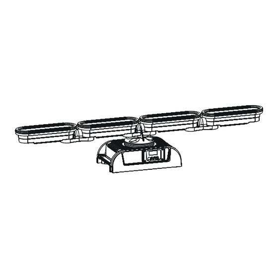
Page 4: Fixture Exterior View
CityFlex 48/CityFlex 48 Wireless DMX The fixture was designed for both indoor and outdoor use. This fixture must not be used for underwater installation. When choosing the installation spot, please make sure that the fixture is not exposed to extreme heat or dust. -
Page 5: Installation
3.1 Rigging the fixture The CityFlex 48 can be rigged in any orientation on a truss without altering its operation characteristics. Installation on the truss allows the mounting adapter (1) fastened to the fixture base with four bolts M8 (2) and the Omega holder (3) for fastening clamp.Pull through the safety rope (4) under the mounting adapter and over the trussing... -
Page 6: Connection To The Mains
CityFlex 48/CityFlex 48 Wireless DMX In case that LED modules and the base are installed separately on the insulant e.g. wall (LED modules and the base are not galvanic interconnected), the LED modules fall under protection class 3 and do not need to be grounded. -
Page 7: Wireless Dmx Operation
3-pin XLR plug with a 120 Ohm resistor soldered between Signal (–) and Signal (+). 3.4 Wireless DMX operation The wireless version of the CityFlex 48 is equipped with the Lumen Radio CRMX module and antenna for receiving DMX signal. CRMX module operates on the 2.4 GHz band. -
Page 8: Cityflex 48 - Dmx Protocol
CityFlex 48/CityFlex 48 Wireless DMX 4. CityFlex 48 - DMX protocol Version 1.4 (Software version 2.8 and higher) Mode/Channel Type of Value Function control Red - all pixels 0-255 Red LEDs saturation control (0-100%) proportional Green - all pixels 0-255... - Page 9 CityFlex 48/CityFlex 48 Wireless DMX Mode/Channel Type of Value Function control Dimmer 3 0-255 Dimmer intensity from 0-100% proportional Red pixel 4 10 13 0-255 Red LED saturation control (0-100%) proportional Green pixel 4 11 14 0-255 Green LED saturation control (0-100%)
- Page 10 CityFlex 48/CityFlex 48 Wireless DMX Mode/Channel Type of Value Function control White pixel 7 0-255 White LED saturation control (0-100%) proportional Dimmer 7 0-255 Dimmer intensity from 0-100% proportional Red pixel 8 22 29 0-255 Red LED saturation control (0-100%)
- Page 11 CityFlex 48/CityFlex 48 Wireless DMX Mode/Channel Type of Value Function control Blue pixel 11 33 43 0-255 Blue LED saturation control (0-100%) proportional White pixel 11 0-255 White LED saturation control (0-100%) proportional Dimmer 11 0-255 Dimmer intensity from 0-100%...
- Page 12 CityFlex 48/CityFlex 48 Wireless DMX Mode/Channel Type of Value Function control Rainbow effect with fade time step Rainbow effect without fade time step Colour effect 1 step Colour effect 2 step Colour effect 3 step Colour effect 4 step Colour effect 5...
-
Page 13: Control Menu Map
CityFlex 48/CityFlex 48 Wireless DMX 5. Control menu map Default settings=Bold print Menu Level 1 Menu Level 2 Menu Level 3 Menu Level 4 Menu Level 5 Menu Level 6 A001 dM.Ad. 001-512 InFo Poti. totL rSEt DM.In. rEd1 0-255... - Page 14 CityFlex 48/CityFlex 48 Wireless DMX Menu Level 1 Menu Level 2 Menu Level 3 Menu Level 4 Menu Level 5 Menu Level 6 Stor. C.c.Mo. On,Off dFSE MAn.M. rEd.1 Uh.12 tESt St.AL. Auto tESt PrG.1 PrG.3 PLAY tESt PrG.1 PrG.3 Edit PrG.1...
-
Page 15: Fixture Menu
4. Press the ENTER button to confirm the choice. Note: After switching on, the CityFlex 48 will automatically detect whether DMX 512 data is received or not. If there is no data received at the DMX input, the display will start to flash with actually set address. -
Page 16: Personality
– software version of each dot (dt.1- dt.12). 6.3 Personality Use this menu to modify the CityFlex 48 operating behaviour. dM.Pr. --- DMX preset. Select this menu item to set a desired DMX mode. Please refer to the chapter "DMX protocol"... - Page 17 CityFlex 48/CityFlex 48 Wireless DMX Example 2 – Pixels are sorted in three rows Example 3 – Four pixels are merged into “one” pixel in each row If two or more pixels have the same pixel position (“dP.1-d.P12”) they will have the same DMX address.
-
Page 18: Manual Mode
CityFlex 48/CityFlex 48 Wireless DMX Upd. --- Pixels update. Besides the main control electronics in the fixture base every pixel contains its own control driver. After standard software updating of the control electronics via the menu “SPEC”, this pixels update has to be performed if some software changes are required in the pixel drivers. -
Page 19: Special Functions
CityFlex 48/CityFlex 48 Wireless DMX 4. Press the ENTER button. 5. Use the UP/DOWN buttons to select desired program. 6. Press the ENTER button to confirm the choice. PLAY --- Playing program. By enter to this menu a complete overview of all programs is offered, from which the program to be run can be selected. - Page 20 DMX input of the fixture if you using the flash cable RS232/DMX with the DMX input of the Robe Universal Interface if you using the USB cable. Disconnect the fixture from the other fixtures in a DMX chain. Turn both the computer and the fixture on.
-
Page 21: Rdm
3. We recommend to cancel all running programs before start of the Software Uploader. 4. Run the Software Uploader program. Select desired COM (or Robe Universal Interface)and then click on the Connect button. If the connection is OK, click on the Start Uploading button to start uploading. It will take several minutes to perform software update. -
Page 22: Error And Information Messages
STATUS_MESSAGES STATUS_ID_DESCRIPTION DEVICE_HOURS Please, see the Robe Universal Interface user manual for detail description of RDM operation. 8. Error and information messages If some error occurs in the fixture, an error message blinks at display. List of error and information messages: Up.dt. -
Page 23: Technical Specifications
CityFlex 48/CityFlex 48 Wireless DMX 9. Technical specifications Power supply • Electronic auto-ranging • Input voltage: 100 - 240V AC, 50-60 Hz • Fuse: T 5A • Max. power consumption: 120W Optic & Effects • Light source: 4 LED modules, each with 3x Cree MC-E RGBW multichip •... - Page 24 CityFlex 48/CityFlex 48 Wireless DMX •LED modules supply: 2x Chogori CGRBB-03RFFS-SC8001 (female) and Chogori CGRBB-03BMMA- SL8001 (male) Rigging • Via omega holder Temperatures • Maximum ambient temperature: 40° C • Maximum housing temperature: 80° C Dimensions (mm) Weight • 6.5 kg Protection factor •...
-
Page 25: Cleaning And Maintenance
CityFlex 48/CityFlex 48 Wireless DMX Beam distribution Note: By reason of the fast-moving development of LED technology, later products may have better light parameters than previous products 10. Cleaning and maintenance DANGER ! Disconnect from the mains before starting any cleaning or maintenance work Rinse off loose dirt with low pressure water spray. - Page 26 CityFlex 48/CityFlex 48 Wireless DMX Specifications are subject to change without notice. April 17, 2013...
Need help?
Do you have a question about the CityFlex 48 and is the answer not in the manual?
Questions and answers