Advertisement
Quick Links
Advertisement

Related Manuals for Corriveau Glendale N101303


Summary of Contents for Corriveau Glendale N101303
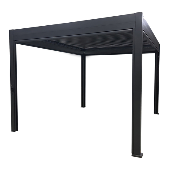
- Page 1 Glendale louver - Louvre Glendale N101303- (2024) Assembly instruction - Plan d’assemblage...
-
Page 2: Important Notice
IMPORTANT NOTICE Pour le français voir pages 4 et 5 Please read and follow all safety statements, warnings, assembly instructions, use & care directions before attempting to assemble. Each of the recommendations must be followed to ensure the utmost solidity. Security Rules Warning : Keep flame and heat sources away from the louver. - Page 3 Care Avoid using a pressure washer. The use of a mild soap with warm water is the best solu- tion for the frame only. A clear water rinse is necessary then. Never use soap on fabric, this will reduce their durability, consequently their lifespan and general look. Warranty Covered : We warrant to the original purchaser for two years.
- Page 4 AVIS Veuillez lire et suivre toutes les notifications relatives à la sécurité, précautions générales, ins- tructions d’assemblage, directives d’utilisation et d’entretien avant de procéder à l’assemblage. Règles de sécurité Avertissement : Tenir toutes flammes ou sources de chaleur éloignées de la louvre. L’armature peut brûler s’il est exposé...
- Page 5 Entretien Ne jamais laver à l’aide d’une machine à pression élevée. On recommande d’utiliser un savon doux combiné à une eau chaude pour le lavage de la structure. Un rinçage à l’eau claire est requis ensuite. Ne jamais utiliser de savon sur les tissus, cette pratique réduirait leurs propriétés et par conséquent leur longévité...
- Page 6 Parts list: Liste de pièce: Drawing Description Illustration QTÉ Post Poteau Post with crank Poteau avec manivelle Crossbar with system Traverse avec système Crossbar with system Traverse avec système Crossbar Traverse Blade Volet Rotation tube Tube de rotation Post cover Couvre poteau Base flange Bride de base...
- Page 7 Parts list: Liste de pièce: Drawing Description Illustration QTÉ Base cover Couvre-base Crank Manivelle Hardware: Quincaillerie: Drawing Description Illustration QTÉ Bolt M6x40mm Vis M6x40mm Bolt M6x16mm Vis M6x32mm Bolt M6x10mm Vis M6x10mm Washer Rondelle Alignment bars Barre d’alignement...
- Page 8 Hardware: Quincaillerie: Drawing Description Illustration QTÉ Bolt M6x14mm Vis M6x14mm Bolt M5.5x20mm Vis M5.5x20mm Cement anchor Ancrage pour ciment Bolt M5x14mm Vis M5x14mm Bolt M5x8mm Vis M5x8mm Bolt M5x10mm Vis M5x10mm Écrou Allen key Clé Allen Nut wrench Clé à écrou...
- Page 9 Hardware: Quincaillerie: Drawing Description Illustration QTÉ Allen key Clé Allen...
- Page 10 A1/A2 M6*16 Step 1: Slide the base covers (H) onto the posts (A1 and A2) from below. Étape 1: Glisser les couvre-base (H) sur les poteaux (A1 et A2) par le bas.
- Page 11 M6*16 A1/A2 Step 2: Bolts can be tightened completely. Fix the base flange (G) to the bottom of the posts (A1 & A2) by using the bolts (BB). Étape 2: Les vis peuvent être serrées complètement. Fixer les brides de base (G) au bas des poteaux (A1 et A2) en utilisant les vis (BB).
- Page 12 M6*40 Ø6 M6*16 Step 3: Bolt can be tightened completely. Fix the crank (I) onto the post (A2) by using the bolts (AA) with a washer (DD). Étape 3: La vis peut être serrée complètement. Fixer la manivelle (I) sur le poteau (A2) en utilisant les vis (AA) avec une rondelle (DD).
- Page 13 M6*10 Ø6 Step 4: Do not tight the bolts completely yet. Fix the alignment bars (EE) on the crossbars with systems (B1 & B2) by using the bolts (CC) with washers (DD). Étape 4: Ne pas serrer les vis complètement pour l'instant. Fixer les barres d'alignement (EE) sur les tra- verses avec système (B1 et B2) en utilisant les vis (CC) avec rondelles (DD).
- Page 14 Step 5: Do not tight the bolts completely yet. Fix the alignment bars (EE) on the crossbars (C1) by using the bolts (CC) with washers (DD). Étape 5: Ne pas serrer les vis complètement pour l'instant. Fixer les barres d'alignement (EE) sur les tra- verses (C1) en utilisant les vis (CC) avec rondelles (DD).
- Page 15 M6*14 90° 90° Step 6: Bolts can be tightened completely. Slide the alignment bars (EE) of the crossbar (B1) into the top of the post (A2) as shown in fig. 3 to 5. Make sure the rod inside the post (A2) is aligned pro- perly inside the crossbar (B1) as shown in fig.
- Page 16 M6*14 M6*14 90° 90° Step 7: Slide the alignment bars (EE) of the crossbar (B2) into the top of the posts (A1) as shown in fig. 1 to 3. Then, fix the alignment bars (EE) by tightening all bolts (CC) as shown in fig 4. Étape 7: Glisser les barres d'alignement (EE) de la traverse (B2) dans la partie supérieure des poteaux (A1) tel qu'illustré...
- Page 17 Step 8: For your safety, you may need 4 people for this step. Align the alignment bars (EE) of the cross- bar (C1) into the top of the posts (A1 & A2) as shown in fig. 1 to 3. Then, fix the alignment bars (EE) by tightening all bolts (CC) as shown in fig 4.
- Page 18 Step 9: Align the alignment bars (EE) of the crossbar (C1) into the top of the posts (A1) as shown in fig. 1 to 3. Then, fix the alignment bars (EE) by tightening all bolts (CC) as shown in fig 4. Étape 9: Glisser les barres d'alignement (EE) de la traverse (C1) dans la partie supérieure des poteaux (A1) tel qu'illustré...
- Page 19 M6*16 M5.5*20 Step 10: Bolts can be tightened completely . Fix the post covers (F) on top of the posts (A1 & A2) by using 4x bolts (BB) & 3x bolts (GG) for post cover (F) as shown in the fig. Étape 10: Les vis peuvent être serrées complètement.
- Page 20 B1=B2 Step 11: Make sure all measurement are the same at the top and bottom of the assembly (refer to fig. 4). Place the louver at the desired place. Then, installs the anchors as shown in the fig. 1 to 3. Use proper anchoring devices.
- Page 21 M5*14 Step 12: Bolts can be tightened completely. Fix the rotation tube (E) to the second rocker arm (counting from the side with the crank) on the crossbars with systems (B1 & B2) by using the bolts (II). Étape 12: Les vis peuvent être serrées complètement.
- Page 22 M5*8 Step 13: Bolts can be tightened completely. Fix the blades (D) until the rocker arm with the rotation tube (E) (starting from the opposite side of the crank) onto the rocker arms (B1 & B2) by using the bolts (JJ) with nuts (LL). Étape 13: Les vis peuvent être serrées complètement.
- Page 23 M5*10 Step 14: Bolts can be tightened completely. Fix the blade (D) to the rocker arms (B1 & B2) with the rota- tion tube (E) by using the bolts (KK) with nuts (LL). Étape 14: Les vis peuvent être serrées complètement. Fixer un volet (D) sur les culbuteurs (B1 et B2) avec le tube de rotation (E) en utilisant les vis (KK) et des écrous (LL).
- Page 24 Bolts can be tightened completely. Fix the remaining blade (D) onto the last set of rocker arms (B1 & B2) using the bolts (JJ) with nuts (LL). We wish you a lot of good moments with your new Corriveau Outdoor furniture louver! Leave us your comments on the Corriveau Outdoor furniture website. We look forward to hearing from you! Étape 15:...
Need help?
Do you have a question about the Glendale N101303 and is the answer not in the manual?
Questions and answers