
Related Manuals for Corriveau B121230


Summary of Contents for Corriveau B121230
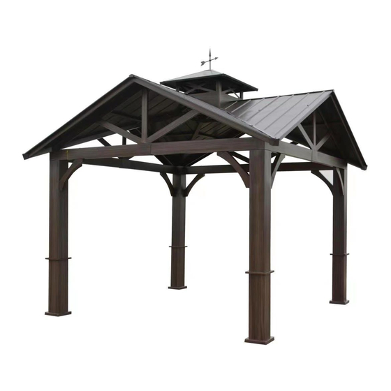
- Page 1 Assembly instructions 12' x 12' Cottage gazebo B121230- MEUBLES DE JARDIN CORRI EAU OUTDOOR FURNITURE...
-
Page 2: Important Notice
Important notice Please read and follow all safety statements, warnings, assembly instructions, use & care directions before attempting to assemble. Each of the recommendations must be followed to ensure the utmost solidity. Security Rules Warning: Keep flame and heat sources away from the gazebo fabric. The fabric may burn or melt at direct contact or prolonged exposure with a source of heat. - Page 3 ●Although this gazebo is built for all year round, the snow must be removed from the roof. ●Mosquito net and curtains (optional) must be removed from the unit in freezing period. ●Anchoring bolts or other anchoring devices are not supplied. ●Keep away from any electric installation or transportation device.
-
Page 6: Parts List
PARTS LIST: Q'TY Description Drawing Post Decor molding Base cover Base plate Left crossbar Right crossbar Corner bracket Corner roof tubing Center roof tubing Roof bracket Crossbar connector Roof support Roof support... - Page 7 Description Drawing Q'TY Right eave Left eave Roof panel Roof panel Roof panel Roof panel Air vent corner tube Air vent side panel Roof cover Corner roof cover Hook Roof connector Corner cover...
- Page 8 Drawing Description Q'TY Roof corner molding Air vent roof panel Air vent roof cover Roof cover Weathervane Stake...
-
Page 9: Hardware Kit
Hardware Kit: Description Drawing Q'TY Bolt M6*30MM M6 X 30mm 80 + 8 Extra M6 X 75mm 4 + 2 Extra Bolt M6*75MM M8 X 95mm Bolt M8*95MM 8 + 2 Extra 8 + 2 Extra Bolt M8*155MM M8 X 155mm Nut M8 8 + 2 Extra Metal washer... - Page 10 Hardware Used: Bolt M6x30mm Allen key Step 1 Insert the base cover (C) onto the post (A). Fix the base plate (D) underneath the post (A) by using two bolts (AA) but do not over tight the bolts. Then put the decor molding (B) onto the post (A) by sliding it from the top.
- Page 11 Hardware Used: Bolt M8x95mm Nut M8 Metal washer Plastic cap Allen Key Spanner Step 2 Insert the left crossbar (E) and the right crossbar (F) into the crossbar connector (K). Fix the assembly by using the bolts (CC), metal washers (FF) (2 by bolts) and the nuts (EE). Bolts can be tightened completely.
- Page 12 Hardware Used: Bolt M6x30mm Allen key Step 3 Bolts can be tightened completely. Fix the crossbar set (E & F) onto two posts (A) by using the bolts (AA).
- Page 13 Hardware Used: Bolt M6x30mm Allen key Step 4 Bolts can be tightened completely. Fix another crossbar set (E & F) by using another post (A) and the post (A) use in step 3 by using the bolts (AA).
- Page 14 Hardware Used: Bolt M6x30mm Allen key Step 5 Bolts can be tightened completely. Fix another crossbar set (E & F) by using another post (A) and the post (A) use in step 3 by using the bolts (AA).
- Page 15 Hardware Used: Bolt M6x30mm Allen key Step 6 Bolts can be tightened completely. Fix the remaining crossbar set (E & F) onto the posts (A) use in step 4 & 5 by using the bolts (AA). ATTENTION: Please measure the distance between all 4 posts (A) and make sure the dimensions are the same as shown in the illustration.
- Page 16 Hardware Used: Bolt M8x155mm Metal washer Allen key Step 7 Bolts can be tightened completely. Install the support corner brackets (G) onto each post (A) (2 by post) and fix the corner brackets (G) onto the crossbar set (E & F) by using the bolts (DD) and metal washers (FF).
- Page 17 Step 8 Insert the corner cover (Z) into the post (A) as shown in the illustration, then secure with the crossbar set (E & F). Repeat this step for all corner covers (Z).
- Page 18 Step 9 Secure the roof brackets (J) together as shown in the illustration.
- Page 19 Step 10 Insert the center roof tubing (I) into the roof brackets set (J), then insert the other end into the crossbar set (E & F). Repeat this step to the other side (180°) as shown in the illustration.
- Page 20 Step 11 Insert the center roof tubing (I) into the roof brackets set (J), then insert the other end into the crossbar set (E & F). Repeat this step to the other side (180°) as shown in the illustration.
- Page 21 Hardware Used: Bolt M6x30mm Bolt M6x40mm Metal washer Plastic washer Allen key Step 12 Do not over tight to bolts. Fix the corner roof tubing (H) to roof brackets (J) by using the bolts (KK) and washers (FF).Then fix the corner roof tubing (H) to the crossbar set (E & F) & post (A) by using the bolts (AA) and the plastic washers (GG).
- Page 22 Hardware Used: Bolt M6x30mm Allen key Step 13 Bolts can be tightened completely. Insert the air vent corner tube (T) into the roof connector (Y), then secure the other end of the air vent corner tube (T) with the corner roof tubing (H). Then fix all the parts previously by using the bolts (AA).
- Page 23 Hardware Used: Bolt M6x30mm Allen key Step 14 Do not tight the bolts completely. Install the left eave (O) into the corner roof tubing (H). Then install the right eave (N) into the corner roof tubing (H). Fix each eave (N & O) with the center roof tubing (I) by using the bolts (AA).
- Page 24 Hardware Used: Bolt M6x30mm Allen key Step 15 Do not tight the bolts completely. Fix the roof support (M) with the corner roof tubing (H) by using the bolts (AA). Then fix the other end to the left eave (O). Repeat those steps for each roof support (M). Then, repeat those steps but for the roof support (L) and the right eave (N).
- Page 25 Hardware Used: Bolt M6x30mm Plastic washer Allen key Step 16 Bolts can be tightened completely. Insert the air vent roof panel (AC) into the air vent corner tube (T), then put the air vent roof cover (AD) onto the air vent roof panel (AC) and the air vent support (T) and fix it by using the bolts (AA) and plastic washers (GG).
- Page 26 Step 17 Fix the weathervane (AF) with the roof cover (AE), then fix the hook (X) underneath the air vent roof.
- Page 27 Hardware Used: Bolt M6x30mm Plastic washer Allen key Step 18 Bolts can be tightened completely. Place the roof panel (P) onto the center roof tubing (I) and corner roof tubing (H). Then do the same for the roof panel (Q). Then align the holes of the roof panels with the anchors of the roof support (M) and fix it by using the bolts (AA) and the plastic washer (GG).
- Page 28 Hardware Used: Bolt M6x30mm Bolt M6x75mm Plastic washer Allen key Step 19 Bolts can be tightened completely. Place the roof cover (V) onto the roof panels (P, Q, R & S) and fix it with the center roof tube (I) by using the bolts (BB) and plastic washers (GG) from the furthest from the center as shown is the illustration.
- Page 29 Step 20 Secure air vent side panel (U) with the air vent corner tube (T) as shown in the illustration. Repeat for all air vent side panel (U).
- Page 30 Hardware Used: Bolt M6x30mm Plastic washer Allen key Step 21 Bolts can be tightened completely. Place the corner roof cover (W) onto the air vent corner tube (T) and fix the corner roof cover (W) with the corner roof tubing (H) by using the bolts (AA) and the plastic washers (GG). Then fix the roof corner molding (AB) with the corner roof tubing (H) by using the bolts (AA) and the plastic washers (GG).
- Page 31 X 16 Step 22 Tight all remaining loose bolts. Step 23 If the gazebo is on soft type ground, insert the stake (AG) through the holes in the base plate (D) into the ground to secure the gazebo. Use the proper anchors for the ground. Please see next page, for example.
- Page 32 Permanent Installation Concrete Patio(min. 12' × 12' ) with 6" clearance on all sides Anchoring Hardware not included Wood Deck (min. 12' × 12' ) with 6" clearance on all sides Anchoring Hardware not included Post Mounts Anchoring Hardware (not included)
Need help?
Do you have a question about the B121230 and is the answer not in the manual?
Questions and answers