Table of Contents
Advertisement
FOR INSTALLER - BEFORE YOU START
To install and operate the Bromic Smart-Heat Control you MUST have access to the following:
•
An app-enabled smart device with internet connectivity.
(Minimum Requirements: Bluetooth 4.2, Android 8.1, iOS 14.3 or greater)
•
The Bromic Smart-Heat App, available for download on the Apple App Store and Google
Play Store using the QR codes below.
•
A Bromic Smart-Heat account or access to email for registration.
•
The name and email address of the primary user.
•
[Wi-Fi only] The SSID and password of a local Wi-Fi network operating on 2.4GHz.
For installation instructions (mounting instructions, mounting orientation, and electrical wiring), refer
to manual.
SCAN FOR
LATEST MANUAL
Bluetooth Control
Controller must be within 10m
(30ft) of heating area for
Bluetooth control
DIFFERENCES BETWEEN BLUETOOTH AND WI-FI COMMUNICATION
BLUETOOTH Communication
•
Controller mounting location must be within
10m (30ft) of the heating location(s).
•
Only 1 smart device may be used at a time.
•
During operation, the smart device must be
within 10m (30ft) of the controller.
•
Enables you to control heaters individually
and use the timer off function.
AU/UK/US_REV 23
App Store
OR
Controller
Wi-Fi installation must be
within 10m (30ft) of router
(or 3 bars signal strength)
Heater
Heating
Area
Smart Device
•
Controller mounting location must be
within 10m (30ft) of a router (or smart
device indicates 3 bars of Wi-Fi at the
mounting location).
•
Enables multiple users simultaneously.
•
Enables off-site control.
•
Enables additional features (Zoning/
grouping and Scene automation).
Play Store
Wi-Fi Control
WI-FI Communication
Wi-Fi Router
Cloud
Advertisement
Table of Contents

Related Manuals for Bromic Heating Smart-Heat Control On/Off 1 CH


Summary of Contents for Bromic Heating Smart-Heat Control On/Off 1 CH
- Page 1 FOR INSTALLER - BEFORE YOU START To install and operate the Bromic Smart-Heat Control you MUST have access to the following: • An app-enabled smart device with internet connectivity. (Minimum Requirements: Bluetooth 4.2, Android 8.1, iOS 14.3 or greater) • The Bromic Smart-Heat App, available for download on the Apple App Store and Google Play Store using the QR codes below.
- Page 3 SMART-HEAT CONTROL BY BROMIC INSTALLATION AND INSTRUCTION MANUAL FOR MODELS: • Smart-Heat Control On/Off 1 CH • Smart-Heat Control On/Off 5 CH • Smart-Heat Control On/Off 2 CH • Smart-Heat Control Dimmer 5 CH • Smart-Heat Control Dimmer 1 CH •...
- Page 4 IMPORTANT This manual contains important information about the installation and operation of the Smart-Heat Controls. Please pay close attention to the important safety information shown throughout this instruction manual. Any safety information will be accompanied by the following safety alert symbols: DANGER, WARNING, IMPORTANT...
-
Page 5: Table Of Contents
CONTENTS IMPORTANT NOTES & WARNINGS PRODUCT DESCRIPTION PRODUCT FEATURES PRODUCT SPECIFICATIONS PACKAGING CONTENTS TOOLS/PARTS REQUIRED INSTALLATION INSTRUCTIONS INSTALLATION CLEARANCES & PRODUCT DIMENSIONS MOUNTING INSTRUCTIONS ELECTRICAL INSTALLATION HEATER TYPES & LOAD DISTRIBUTION WIRING DIAGRAMS OPERATING INSTRUCTIONS APP SETUP REGULAR USE MAINTENANCE VOICE ACTIVATION AMAZON ALEXA INSTRUCTIONS GOOGLE HOME INSTRUCTIONS... -
Page 6: Important Notes & Warnings
IMPORTANT NOTES & WARNINGS WARNING • This controller is NOT intended to be installed on recreational vehicles and/or boats. • Read all instructions before installing or using this controller. • Do not run cords under carpeting. Do not cover with throw rugs, •... -
Page 7: Product Description
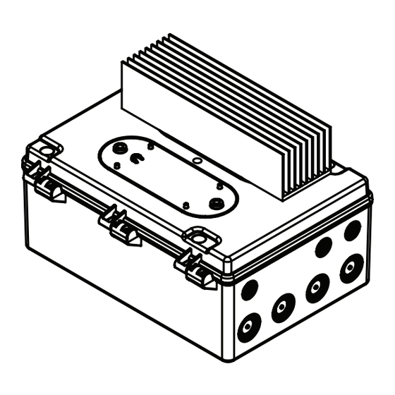
PRODUCT DESCRIPTION The Smart-Heat Control provides on/off or dimming control for Bromic heaters. The Smart-Heat Control requires a smart device with internet connectivity, as well as the Bromic Smart-Heat App which is available on the App Store and Google Play Store. The base model provides both Bluetooth and Wi-fi communication capabilities, with optional expansion board available for alternative communication methods (ethernet or 0 - 10 V DC input control from Building Management Systems (BMS) or home automation). - Page 8 PRODUCT SPECIFICATIONS - DIMMER MODELS Model Smart-Heat Control Smart-Heat Control Smart-Heat Control Dimmer 1 CH Dimmer 2 CH Dimmer 5 CH Part Number BH3130061 BH3130062 BH3130063 Number of Channels Supply a.c. 50-60Hz a.c. 50-60Hz a.c. 50-60Hz Supply Phase Single Phase Single or 2 Phase 3 Phase Voltage - Max Capacity Per Channel...
-
Page 9: Packaging Contents
PACKAGING CONTENTS PACKAGING CONTENTS Controller Smart-Heat Control On/O 1 CH Smart-Heat Control Dimmer 1 CH Smart-Heat Control Dimmer 2 CH Smart-Heat Control On/O 2 CH Smart-Heat Control Eclipse Pendant 1 CH Smart-Heat Control On/O 5 CH Smart-Heat Control Dimmer 5 CH Smart-Heat Control Eclipse Pendant 5 CH Instruction Manual... -
Page 10: Tools/Parts Required
PACKAGING CONTENTS Model Accessory Bag Contents On/Off 1-Channel 2 x M25 Cable Gland (4 x supplied with 2-Channel) & 5 x M4x10 Screw On/Off 2-Channel 5 x Spring Washer & Eclipse Pendant 1-Channel Dimmer 1-Channel 2 x M25 Cable Gland (4 x supplied with 2-Channel) &... -
Page 11: Installation Instructions
150 (6) 150 (6) in mm (inches) PRODUCT DIMENSIONS Smart-Heat Control On/Off 1 CH Smart-Heat Control Dimmer 1 CH Smart-Heat Control On/Off 2 CH Smart-Heat Control Dimmer 2 CH Smart-Heat Control Pendant Eclipse 1 CH 202 (8.0) 202 (8.0) -
Page 12: Mounting Instructions
On/Off models do not have a height clearance requirement. Wall Mounting Wall Mounting suitable for below models: • Smart-Heat Control On/Off 1 CH • Smart-Heat Control On/Off 2 CH • Smart-Heat Control On/Off 5 CH •... - Page 13 MOUNTING INSTRUCTIONS PROCEDURE for models: Smart-Heat Control Dimmer 1 CH • Smart-Heat Control On/Off 1 CH • Smart-Heat Control Dimmer 2 CH • Smart-Heat Control On/Off 2 CH • • Smart-Heat Control Eclipse Pendant 1 CH IMPORTANT Refer to the applicable controller weight on pages 7-8 and for wall mounting, ensure an appropriate length for the screw fixings.
-
Page 14: Electrical Installation
ELECTRICAL INSTALLATION IMPORTANT NOTES AND WARNINGS WARNING This control MUST be installed by an authorized/licenced person. Do not carry out installation or assembly procedure while electrical power is switched on. DANGER ELECTRICAL SHOCK HAZARD! Serious injury or death may occur. Disconnect from electrical supply before installing or servicing this heater. -
Page 15: Heater Types & Load Distribution
HEATER TYPES & LOAD DISTRIBUTION For On/Off and Dimmer models, use the tables below to determine the channel capacity and ensure that the total connected load does not exceed maximum channel rating. For Smart- Heat Control Eclipse Pendant models, only install one Eclipse Pendant per controller. Ensure all circuits are labelled for ease of identification. - Page 16 HEATER TYPES & LOAD DISTRIBUTION CONTINUED... If you intend to control two elements from a single heater independently, refer to the element loads below, as well as applicable heater instruction manual for wiring diagrams. If this is not the case simply refer to the total appliance load listed below. Step 3 –...
-
Page 17: Wiring Diagrams
WIRING DIAGRAMS - ON/OFF MODELS WIRING DIAGRAM FOR SMART-HEAT CONTROL ON/OFF 1CH • Connect power source and heater to screw terminals as displayed with a torque of 1.3Nm (1ft-lbs). The terminal size is 10mm / 8AWG. • Connect ground to internal busbar with fasteners provided. Tighten with max torque 3Nm (2.22 ft-lbs). •... - Page 18 WIRING DIAGRAM FOR SMART-HEAT CONTROL ON/OFF 2CH • Connect power source and heater to screw terminals as displayed with a torque of 1.3Nm (1ft-lbs). The terminal size is 10mm² / 8AWG. • Connect ground to internal busbar with fasteners provided. Tighten with max torque 3Nm (2.22 ft-lbs). •...
- Page 19 WIRING DIAGRAMS - DIMMER MODELS WIRING DIAGRAM FOR SMART-HEAT CONTROL DIMMER 1CH • Connect power source and heater to stud using M6 ring terminals as displayed. The ring terminals must be UL certified and tightened to 6-7Nm (4.5-5.2 ft-lbs). • Connect ground to internal busbar with fasteners provided.
- Page 20 WIRING DIAGRAM FOR SMART-HEAT CONTROL DIMMER 2CH • Connect power source and heater to stud using M6 ring terminals as displayed. The ring terminals must be UL certified and tightened to 6-7Nm (4.5-5.2 ft-lbs). • Connect ground to internal busbar with fasteners provided. Tighten with max torque 3Nm (2.22 ft-lbs). •...
- Page 21 WIRING DIAGRAM FOR SMART-HEAT CONTROL DIMMER & ON/OFF 5CH 3 Phase/3 Wire - 120/208V Line to Line, 100/200V Line to Line, Split 240V • Straight links from accessory bag must be fitted by installer for heater connection • Suitable for North America (120V to 120V), Japan (100V to 100V). HOT 3 (L3) HOT 2 (L2) HOT 1 (L1)
- Page 22 WIRING DIAGRAM FOR SMART-HEAT CONTROL DIMMER & ON/OFF 5CH (Bromic 240V or 277V Heaters) 3 Phase/4 Wire - Line to Neutral Connection - 220/380V, 230/400V, 240/415V, 277/480V * Neutral connection is made by fitting the L shape link from accessory bag. * Suitable for: Australia (230/240V) / Europe (220/230/240V) / India (230V) / US (277V) NEUTRAL HOT 3 (L3)
- Page 23 WIRING DIAGRAMS - ECLIPSE PENDANT MODEL WIRING DIAGRAM FOR SMART-HEAT CONTROL ECLIPSE PENDANT 1CH • Connect power source and heater to screw terminals as displayed, with a torque of 0.6Nm (0.4ft-lbs). The terminal size is 6mm² / 10AWG. • Connect ground to internal busbar with fasteners provided. Tighten with max torque 3Nm (2.22 ft-lbs). •...
- Page 24 WIRING DIAGRAM FOR SMART-HEAT CONTROL ECLIPSE PENDANT 5CH 3 Phase/3 Wire - 240V Line to Line (No Neutral Connection) • Straight links from accessory bag must be fitted by installer for heater connection • Suitable for North America (120V - 120V) HOT 3 (L3) HOT 2 (L2) HOT 1 (L1)
- Page 25 WIRING DIAGRAM FOR SMART-HEAT CONTROL ECLIPSE PENDANT 5CH 3 Phase/4 Wire - Line to Neutral Connection 240V * Neutral connection is made by fitting the L shape link from accesory bag. * Suitable for North America (240 Only) NEUTRAL HOT 3 (L3) HOT 2 (L2) HOT 1 (L1) bromic.com...
- Page 26 WIRING DIAGRAM FOR SMART-HEAT CONTROL ECLIPSE PENDANT 5CH JUNCTION BOX & LED WIRING 24V DC (+) 0V DC (-) 24V DC (+) 0V DC (-) 24V DC (+) 0V DC (-) 24V DC (+) 0V DC (-) 24V DC (+) 0V DC (-) BROWN BROWN...
-
Page 27: Operating Instructions
OPERATING INSTRUCTIONS APP SETUP Download the Bromic Smart-Heat App from the Apple App Store or Google Play Store. When opened, the Bromic Smart-Heat App will prompt you to register an account before guiding you through the configuration of your site. Note that each Smart-Heat Control requires its own setup. -
Page 28: Voice Activation
VOICE ACTIVATION All models of the Bromic Smart-Heat Control are compatible with Amazon Alexa and Google Home. Note: You must already have an Amazon or Google Home account prior to linking your device. AMAZON ALEXA INSTRUCTIONS 1. Open the Amazon Alexa App and select the ‘More’ tab. -
Page 29: Expansion Board Installation
EXPANSION BOARD INSTALLATION The Bromic Smart-Heat Control expansion board enables additional connection types like Ethernet and BMS for home automation and Building Management System applications. For 1-Channel and 2-Channel models the expansion board is an accessory (sold seperately). For 5-Channel models the expansion board is included pre-installed with the controller. The following section outlines the process to install the expansion board for 1-Channel &... -
Page 30: Ethernet Connection
EXPANSION BOARD CONNECTIONS IMPORTANT ELECTRICAL SHOCK HAZARD. Disconnect power beforemaking Incorrect polarity or short circuit will connections to the PCB damage the expansion board. ETHERNET CONNECTION An ethernet connection is offered for wired connection to a home router or gateway using DHCP (static or dynamic). -
Page 31: Troubleshooting
TROUBLESHOOTING SYMPTOM POSSIBLE CAUSE(S) CORRECTIVE ACTION(S) App is unresponsive/ Too many requests in a short pe- Close and reopen Bromic Smart-Heat frozen riod of time. App. 2. App or phone operating system 2. Complete a software update on both may be out of date/incompatible. smart device and Smart-Heat App.
Need help?
Do you have a question about the Smart-Heat Control On/Off 1 CH and is the answer not in the manual?
Questions and answers