
Related Manuals for Cuisinart G41804


Summary of Contents for Cuisinart G41804
- Page 1 This Owner's Manual is provided and hosted by Appliance Factory Parts. CUISINART G41804 Owner's Manual Shop genuine replacement parts for CUISINART G41804 Find Your CUISINART Grill Parts - Select From 152 Models -------- Manual continues below --------...
-
Page 2: Assembly Manual
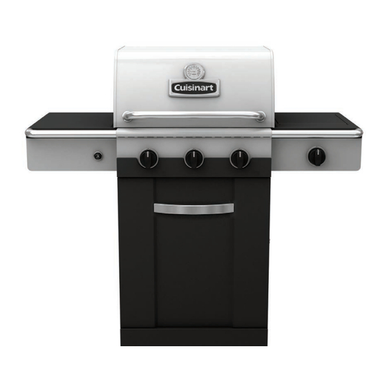
85-3078-6 (G41803) Propane Cuisinart Gourmet 600S ® 85-3079-4 (G41804) Natural Gas READ AND SAVE MANUAL FOR FUTURE REFERENCE. Assemble your grill immediately. Missing or damaged parts should be claimed within 30 days of purchase. For product inquiries, parts, warranty and troubleshooting support, please call 1-800-309-3452. - Page 3 H E A V Y A R T I C L E N E E D S 2 T O L I F T THIS MANUAL MUST REMAIN WITH THE PRODUCT AT ALL TIMES To ORDER non-warranty replacement parts or accessories, or to register your warranty, please visit us on the web at www.cuisinartbbqs.com CAUTION...
- Page 4 PARTS LIST (PROPANE) FOR 85-3078-6 (G41803) Item No. Qty. Description Part No. Item No. Qty. Description Part No. Top Lid G418-2000-01 Side Shelf Table, Left G525-0700-01 Lid Handle G412-0035-02 Side Shelf Fascia, Left G418-0600-01 Thermometer G512-0085-01 Towel Bar G525-0029-01 Screw for Top Lid G501-0005-02 Multi Spark™...
- Page 5 PARTS LIST (NATURAL GAS) FOR 85-3079-4 (G41804) Item No. Qty. Description Part No. Item No. Qty. Description Part No. Top Lid G418-2000-01 Side Shelf Table, Left G525-0700-01 Lid Handle G412-0035-02 Side Shelf Fascia, Left G418-0600-01 Thermometer G512-0085-01 Towel Bar G525-0029-01...
- Page 6 ASSEMBLY INSTRUCTIONS Separate the 2 different types of wheels: 2 Locking Wheels (EE) and 2 regular Wheels (EF). Insert the U Pin (#7) into one of the regular Wheels (EF), as shown in image B. Attach the regular Wheel (EF) to the front of the Bottom Shelf (ED), and use the U Pin (#7) to secure and tighten.
- Page 7 ASSEMBLY INSTRUCTIONS THIS STEP REQUIRES 3 OR MORE PEOPLE. DO NOT ATTEMPT ALONE. EXTREMELY HEAVY. a. Position the Top Lid and Burner Box Assembly (A and B) onto the Cart Assembly (C), as shown. TIP: Ensure that the Front Brace (CK) is positioned under the Control Panel (CF).
- Page 8 ASSEMBLY INSTRUCTIONS a. Assemble the Towel Bar (DC) to the Control Panel (CF) and Left Side Shelf Table (DA), as shown in figure A & B. YOU WILL NEED: b. Attach the two Ignition Button wires to the Multi Spark™ Ignition Button (DD), as shown in figure C.
- Page 9 ASSEMBLY INSTRUCTIONS a. Assemble the side burner control knob bezel (#13) to the right side shelf fascia (DF) as shown in figures A. YOU WILL NEED: b. Remove the hardware that is pre-assembled to the Side Burner Valve Bracket (CL), as shown in figure B.
- Page 10 ASSEMBLY INSTRUCTIONS d. Attach the end of the Side Burner Electrode Wire (DI) to the underside of the Side Burner (DH), as shown in figure E. Ensure that the wire is pushed in firmly. e. Place the Side Burner Cooking Grate (DK) into position on the Side Shelf (DE), as shown in figure F.
- Page 11 ASSEMBLY INSTRUCTIONS a. Remove the Electronic Ignition Battery Cap (CD2) and the plastic nut from the Electronic Ignition Box (CD1). b. Feed the Electronic Ignition Assembly (CD1) through the opening in the Left Cart Side Panel (EA) and secure using the nut. c.
- Page 12 ASSEMBLY INSTRUCTIONS a. Assemble the Door Assembly (EC), to the bottom Shelf (ED) by inserting the fixed pin (bottom of door) into the hole provided as shown in Figure B. Close up b. Assemble the top of the Door Assembly (EC) to the Front Brace (CK), by pressing in the door support pin and aligning with the hole located on the top right corner of the door,...
- Page 13 Attach the Regulator coupling nut (CB) to the LP cylinder valve. Be careful not to cross thread. Hand tighten only. d. Perform leak test. See page 4 of the Cuisinart Safety & Care Manual. ® ATTENTION: For your families safety,...
-
Page 14: Join The Conversation
Visit www.cuisinartbbqs.com to complete product registration. Cuisinart Gourmet Barbecues Customer Service: ® 1-800-309-3452 Join the conversation facebook.com/cuisinartbbqs twitter.com/cuisinartbbqs Cuisinart is a registered ® trademark used under license © 2013 Trileaf Distributions Trifeuil...
Need help?
Do you have a question about the G41804 and is the answer not in the manual?
Questions and answers