Table of Contents
Advertisement
Quick Links
Advertisement
Table of Contents

Related Manuals for Weltem WPC-15000S


Summary of Contents for Weltem WPC-15000S
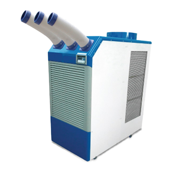
- Page 1 Portable Air Conditioners SERVICE MANUAL WPC-15000S...
-
Page 2: Table Of Contents
WPC-15000S Service Manual Table of Contents GENERAL DESCRIPTION..................4 General air conditioning system Portable air conditioning system SPECIFICATIONS....................5 Exterior Dimension Diagram Technical Specifications CONSTRUCTION.....................8 Internal Structure REFRIGERANT SYSTEM CONSTRUCTION............9 Compressor Compressor operation Compressor lubrication Condenser Expansion valve Evaporator ELECTRICAL SYSTEM..................15 Circuit Diagram... - Page 3 WPC-15000S Service Manual ASSEMBLY.....................28 General Safety Information Troubleshooting chart DISASSEMBLY....................33 Disassembly Control panel removal Electrical parts and relay board removal Fan motor removal REFRGERANT SYSTEM REPAIR...............40 Brazing Charging the System with R-410A Refrigerant Connection of gauge manifold Evacuation Refrigerant Charging Work...
-
Page 4: General Description
Indoor Unit Outdoor Unit Condenser Evaporator Portable air conditioning system 1) The WPC-15000S is a spot cooler which directs cool air to particular areas or objects. Exhaust Hot Air 2) The WPC-15000S has the following features. 3) The innovative design of the WPC-15000S... -
Page 5: Specifications
WPC-15000S Service Manual SPECIFICATIONS Exterior Dimension Diagram (WPC-15000S) mm(Inch) 715(28.1) page 5... - Page 6 WPC-15000S Service Manual SPECIFICATIONS Exterior Dimension Diagram (WPC-15000S) mm(Inch) 1100(43.3) 6 page...
-
Page 7: Technical Specifications
WPC-15000S Service Manual Technical Specifications Specifications WPC-15000S Power Supply Ph-V-Hz Single Phase, 220V, 60Hz Cooling Capacity Btu/h 60,000 Power Consumption Watts 6,260 Rated Current Amps 28.49 EER Btu/Wh 9.58 Nema Plug 6-50P Power Cord Gauge AWG Power Cord Length ft Dimensions W x D x H - in. -
Page 8: Construction
WPC-15000S Service Manual CONSTRUCTION Internal Structure (WPC-15000S) Cond Cowl Top Cover Rear Nozzle Ass'Y RH Cover Rear Top Cover Front Cond Filter Cond Top Plate RH Condenser Air BKT Cond Duct Display Cond Fan / Motor Cond Motor BKT D... -
Page 9: Refrigerant System Construction
WPC-15000S Service Manual REFRIGERANT SYSTEM CONSTRUCTION Condenser Evaporator Compressor Expansion Valve Drier page 9... -
Page 10: Compressor
WPC-15000S Service Manual Compressor A scroll compressor is a piece of machinery inside your HVAC unit that compresses gaseous refrigerant so that it can pass through your refrigerant coil and be sent into your home to cool the air. A scroll compressor is a type of compressor that uses two interlaced spiral metal pieces (or scrolls) instead of pistons to compress the refriger- ant. -
Page 11: Compressor Operation
WPC-15000S Service Manual Compressor operation 1) Start of compression Discharge 1) The cylinder is filled with low pressure gas. Blade Valve 2) Since pressure in the discharge chamber is higher than in the cylinder, the dis- charge valve is kept closed. -
Page 12: Compressor Lubrication
WPC-15000S Service Manual Compressor lubrication The lubrication system is comprised of a hollow shaft, an oil scraper mounted at the end face, hollow shaft, a shaft journal (shaft bearing), and the lubrication groove for the shaft journal. Rotor The lubrication groove is wider than the oil hole. -
Page 13: Expansion Valve
WPC-15000S Service Manual Expansion valve A thermostatic expansion valve is a refrigeration and air conditioning throttling device that controls the amount of refrigerant liquid injected into a system’s evaporator—based on the evaporator outlet temperature and pressure Evaporator The evaporator is a heat exchanger covered with slit fins. -
Page 14: Electrical System
WPC-15000S Service Manual agram ELECTRICAL SYSTEM Circuit Diagram (WPC-15000S) WPC-15000S CL/EL HIGH PRESSURE SWITCH Power Remote Control (Option) PUMP' SEN1 OUT_TEMP MCCB SENSOR IN_TEMP SEN2 SENSOR ICE_TEMP SEN3 SENSOR fuse1.fuse2 : 220V / 3.15A Power 1P AC 220V-60Hz MC 1... -
Page 15: Control Panel
WPC-15000S Service Manual Control panel Before operating the unit, it is important to be familiar with the basic operation of the control panel. 1. POWER BUTTON • Activates unit when POWER BUTTON is pressed. • Fan starts on low speed. - Page 16 WPC-15000S Service Manual 5. SET TEMP BUTTON • Change target temperature / data value by ± 1. • Change data value by ± 10 by pressing continually. • Press the SET TEMP BUTTONS to set temperature. • Upper button is to heighten temperature and Lower button is to lower temperature.
-
Page 17: Program Setting
WPC-15000S Service Manual Program Setting Temperature Se ng Program Se ng (Auto restored when no se ng is made in each mode) Keep depressing more than Temperature 3 seconds dependence Delay me Change Change Change Target Temperature Devia on Power Switch... -
Page 18: Relay Board
The relay board contains the compressor and fan on relays, in addition to a step- down transformer that converts the line voltage (WPC-15000S: 208/230 VAC) to 12V. This voltage is then converted from AC to DC and used for relay coil activation. -
Page 19: Control Panel Input
WPC-15000S Service Manual 3) Input Signal The relay board receives inputs from the control panel, sensors, and external devices to perform device control. Control Panel Input Symbol Indication Function Connector If POWER BUTTON is pressed during operation, unit ON/OFF Button stops. -
Page 20: Control Specifications
WPC-15000S Service Manual Control Specifications 1) EVAPORATOR FAN MOTOR • When the BLOWER button is pressed, the RL1/3 (fan motor HI/LOW) relay on the relay board turns on, operating the fan. Specifications: - RL1/3 (Fan motor HI-LOW) relay output: 10 A at AC 250 V 2) Compressor start control •... - Page 21 WPC-15000S Service Manual 4) Compressor time delay control (compressor protection) Compressor protection consists of a time delay program within the microproces- sor. This program prevents a heavy load from being applied to the compressor motor when restarting the unit (room/cool mode or spot/cool mode) after a very short period of time.
-
Page 22: Self-Diagnostic Codes
WPC-15000S Service Manual Self-Diagnostic Codes Self-diagnostic codes are displayed on the Display Panel under the following conditions. SELF-DIAGNOSTIC ALARM CODES Alarm Code Possible Causes What To Do • High ambient • Ambient temperature temperature must be under 113°F(45°C) Compressor • Unstable power •... - Page 23 WPC-15000S Service Manual SELF-DIAGNOSTIC ALARM CODES Alarm Code Possible Causes What To Do • Do not use the air Indoor heat conditioner if ambient Frost on heat exchanger temperature is lower than exchanger temperature too 64°F(18°C) • Contact a qualified...
-
Page 24: Compressor
WPC-15000S Service Manual Compressor 1) Compressor motor • The compressor motor is a single-phase motor and is contained within the same housing as the compressor. Specifications: Rated Voltage CAPACITY WPC-15000S 220 V 20,456W ±5% 2) Compressor overload relay • The compressor overload relay is used to protect the compressor motor. -
Page 25: Fan Motor
WPC-15000S Service Manual Fan Motor • The fan motor is a single phase, induction type. The motor rotates the fan on both the evapora- tor side and the condenser side at the same time. • The following table shows the specifications of the fan motor used for each model. -
Page 26: Temperature Sensor
WPC-15000S Service Manual Temperature Sensor • Outlet temp sensor (TH1) is installed on top of the evaporator, and detects evaporator outlet temperature as a resistance value. • Inlet temp sensor (TH2) is installed in front of evapo- rator, and detects evaporator inlet temperature as a resistance value. -
Page 27: Drain Pump
WPC-15000S Service Manual Drain Pump • Drain pump is the device that drain the condensate automatically, when the wa- ter level caused by heat exchanging is rising up. • Check the drain pump defective or improper hose connection, when the alarm code is “Fd”... -
Page 28: Assembly
WPC-15000S Service Manual ASSEMBLY Cool air outlet Top fan exhaust flange Handle Display / Control board Condenser / filter Evaporator / filter Condenser / filter Electrical access panel Drain pump included Drain pump hose connector Caster Figure 2 Figure 3 Front and Right Side View Back and Le�... -
Page 29: General Safety Information
WPC-15000S Service Manual General Safety Information Please read this manual carefully for instructions on correct installation and usage. Please read all safeguards. 1. Transport and store the unit in an upright position only. Leave unit in an upright position for at least 3 hours before first use. - Page 30 WPC-15000S Service Manual 17. AVOID the use of adapter plugs or extension cords. If it is necessary to use an extension cord or an adapter plug to operate the unit, ensure that they are correctly rated for the application. Consult a local qualified electrician and all local electrical codes to ensure proper setup.
-
Page 31: Troubleshooting Chart
WPC-15000S Service Manual Troubleshooting chart Symptom Possible Cause(s) Corrective Action Position issue / 1. Check the water tank is placed on the correct position Replace Damage the damaged water tank with the new one. 2. Remove any object stuck Water leakage... - Page 32 WPC-15000S Service Manual Symptom Possible Cause(s) Corrective Action Compressor will not 1. Wait 3 minutes after unit is work if the unit is turned off before turning turned off and on the unit back on. quickly. 2. Check the Cool Icon...
-
Page 33: Disassembly
WPC-15000S Service Manual DISASSEMBLY Disassembly 1) Remove the after turning off the circuit breaker (For Safety) Cooling Air Duct 2) Take out the twelve (2) screws, and remove front panel. 3) Take out the twelve (12) screws, and then Screws (12) remove the cooling air duct. - Page 34 WPC-15000S Service Manual 6) Take out the nine (13) screws, and Cooling Air Duct then remove the back cover. Screws (12) Front Panel Screws (13) Back Cover 7) Take out the nine (15) screws, and Screws (4) then remove the cover top Rear.
- Page 35 WPC-15000S Service Manual 11) Remove the air filter from the back panel.Take out the thirteen (12) screws, and then remove the LF Cover rear. 12) Take out the seven (10) screws, and then remove the RH Cover front. Screws (12)
-
Page 36: Control Panel Removal
WPC-15000S Service Manual Control Panel Removal 1) Take out the four (4) screws, and then remove the control panel. Screws (4) Control Panel 36 page... -
Page 37: Electrical Parts And Relay Board Removal
WPC-15000S Service Manual Electrical parts and relay board removal ( WPC-15000S ) page 37... - Page 38 WPC-15000S Service Manual ( WPC-15000S ) Control Box Terminal Block Circuit Breaker Aluminum Channel Magnetic Contactor Space Support Compressor Capacitor Main PCB Relay Socket Relay Socket Over Current Relay Relay 38 page...
-
Page 39: Fan Motor Removal
WPC-15000S Service Manual Fan Motor Removal (Model : WPC-15000S) 1) Cond Duct Air Guide B 2) Cond Motor BKT RH 3) Cond Motor BKT LF Air Guide A Eva Cover Top Cond Motor / Fan 4) Eva Duct Barrier 6) Eva Motor LF BKT... -
Page 40: Refrgerant System Repair
WPC-15000S Service Manual REFRIGERANT SYSTEM REPAIR Brazing • In the event of a leak, obstruction, or trouble in the refrigerant system of the unit, replace or repair the defective component. After replacing defective component, braze all connections. 1) Proper brazing techniques •... - Page 41 WPC-15000S Service Manual 3) Cleaning brazing filler metal and piping • When the refrigerant system has been opened, exposure to heat may cause the brazing filler metal to stick to the inside and outside of the piping. Brazing filler metal may also combine with oxygen in the air to form an oxide film. In addition, grease and oils may stick to the pipe during handling.
-
Page 42: Charging The System With R-410A Refrigerant
WPC-15000S Service Manual Charging the System with R-410A Refrigerant • Always ensure that the refrigerant system has been properly evacuated before charging with the specified amount of R-410A. • Equipments is only for R-410A. • Liquid charge (no gas charge). -
Page 43: Connection Of Gauge Manifold
WPC-15000S Service Manual Connection of gauge manifold 1) Properly remove the crushed end of the pinch-off tube at the high pressure side and Charging Hose Side the low pressure side of the refrigerant cycle Refrigerant with a pipe cutter. Cycle Side 2) Fit the process tube fitting to the pinch-off tube on both sides. -
Page 44: Refrigerant Charging Work
Charge the system with refrigerant to the specified amount. Standard Amount of Refrigerant: - WPC-15000S : 98.8 oz ( 2,800 g ) The amount of refrigerant charged has a great effect on the cooling capacity of the unit. Charge to the specified... - Page 45 WPC-15000S Service Manual WARNING •Do not attempt any repair on a charged system. WARNING • Before checking for gas leaks, fully confirm that there is nothing flammable in the area to cause an explosion or fire. Contact of refrigerant with an open fire generates toxic gas.
- Page 46 154, Jayumuyeok 3-gil, Masanhoewon-gu, Changwon-City, Gyeongsangnam-do, 51340 Korea TEL: +82-55-294-9200(ext.2) FAX: +82-55-294-9220 http://www.weltem.com...
Need help?
Do you have a question about the WPC-15000S and is the answer not in the manual?
Questions and answers