Table of Contents
Advertisement
Quick Links
(http://www.watanabe-electric.co.jp/en/)
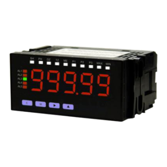
1/8 DIN Digital Panel Meter for Process
(Single Display)
WPM-1-
Instruction Manual
1. Precautions .................................................. 1
2. Ordering information ..................................... 1
3. Installation .................................................... 2
4. Terminal connections .................................... 2
5. Component names and functions ................. 4
6. Character representation .............................. 4
7. Operation procedure diagram ....................... 5
8. Built in excitation settings ............................. 6
9. Measurement range settings ........................ 6
Setup
1. Precautions
1-1. Operating environment and conditions
Please do not install the device in the following locations. It may damage the device or shorten the life.
Locations out of operating temperature range -5 to 50°C.
1)
Locations out of operating humidity range 35 to 85%, or locations where freezes / condenses.
2)
Locations with high concentrations of dusts, metal powders etc.
3)
(Required measures against heat radiation and storage to the dust-proof case.)
Locations with corrosive gas, salinity or soot.
4)
Locations which has a influence of vibration or impact.
5)
Locations where the unit may come in contact with rain or water drop. (except the front bezel)
6)
Locations with a strong electromagnetic fields or exogenous noise.
7)
1-2. Mounting and connection
Please read this manual before installation and connection. Also, please install and connect by the person who has professional skills.
1)
The insulation class of this unit is as below. Please check the insulation class satisfies the requirement before installation.
Basic insulation
Comparative output
Power
Input
supply
External control, Analog output
Do not connect power connect line, input signal line and output signal line near the noise source or the relay driving line.
2)
Connecting with the noise superimposed line or storing in the same duct may cause operation failures.
3)
This unit is available as soon as the power supplied, but needs 30 minutes electrification to show the best performance.
4)
1-3. Check before using
Installation location must meet the requirement of operating conditions and operating environments.
Please inspect the product for any signs of shipping damage and contact your dealer or Watanabe Electric Industry Co., Ltd if anything comes to
your attention.
2. Ordering information
2-1. Ordering code
The ordering code of the WPM-1 is shown below. Please check that the product received matches the product ordered.
WPM - 1 -
Code
Power supply
Code
1
100 to 240Vac
1
2
□
□□
□□□
1-B
-
-
Display
Code
Input range
Single
DC voltage
1
(11 to 14 range)
Multi
DC high voltage
2
(15 range)
DC current
3
(21 to 24 range)
DC large current
4
(25 range)
B
Process signal
Contents
10. Scaling settings .......................................... 7
11. Analog output ............................................. 8
12. Comparative alarm function ......................10
13. External control function ........................... 11
14. Initialize set values ....................................13
15. Troubleshooting (Error codes) ...................13
16. Specifications............................................14
17. Parameter list ............................................16
-
0 0
Code
Output
Code
0
Display only
0
None
1
Analog output
2 setpoints
1
Relay output
4 setpoints
2
Relay output
2 setpoints
3
Photo coupler output
4 setpoints
4
Photo coupler output
IP66 rating
(Front Bezel)
Comparative
Code
Test report
output
0
None
With
1
Test report
1/19
Advertisement
Table of Contents

Related Manuals for WATANABE WPM-1 1-B Series


Summary of Contents for WATANABE WPM-1 1-B Series
-
Page 1: Table Of Contents
1-3. Check before using Installation location must meet the requirement of operating conditions and operating environments. Please inspect the product for any signs of shipping damage and contact your dealer or Watanabe Electric Industry Co., Ltd if anything comes to your attention. -
Page 2: Installation
□ □□ □□□ Instruction manual MODEL WPM-1- 2/19 2-2. Accessories Please check if you have all the accessories below. Protective cover for terminal block ‘Display only’ / ‘with Analog output’ : 2pcs, with Comparative output : 3pcs 3. Installation 3-1. Panel cutout dimensions Panel cutout is as the diagram shown below. - Page 3 □ □□ □□□ Instruction manual MODEL WPM-1- 3/19 4-2. Upper terminal connections (External control / analog output) Voltage output External control terminal Terminal Name Description Current output External control terminal 1 External control terminal 2 External control terminal 3 External control terminal 4 15,16 External control common terminal V OUT...
-
Page 4: Component Names And Functions
□ □□ □□□ Instruction manual MODEL WPM-1- 4/19 Photo coupler 4 setpoints photo coupler output Terminal Name Description output AL1c AL1 comparative output terminal Collector AL1,2 e AL1/AL2 comparative output common terminal Emitter AL2 c AL2 comparative output terminal Collector AL3 c AL3 comparative output terminal Collector... -
Page 5: Operation Procedure Diagram
□ □□ □□□ Instruction manual MODEL WPM-1- 5/19 Operation 7. Operation procedure diagram... -
Page 6: Built In Excitation Settings
□ □□ □□□ Instruction manual MODEL WPM-1- 6/19 8. Built in excitation settings The default setting for built in excitation (sensor power supply) is 12Vdc (100mA) when you purchase. Please change the setting if you want to use with 24Vdc(50mA). Note : Built in excitation will be shut off when more than rated load was connected to the built in excitation. -
Page 7: Scaling Settings
□ □□ □□□ Instruction manual MODEL WPM-1- 7/19 Power up 電源投入 (Measurement mode) (測定状態) 電源投入 電源投入 (測定状態) (測定状態) Hold the [ENTER] key down for 3 seconds when ①測定動作中にエンターキーを3秒長押しする。 長押し(3秒) 3 sec min. Measurement mode. ①測定動作中にエンターキーを3秒長押しする。 ①測定動作中にエンターキーを3秒長押しする。 長押し(3秒) 長押し(3秒) ②モードキーを押すとパターン名が表示される。 電源投入 ②モードキーを押すとパターン名が表示される。... -
Page 8: Analog Output
(測定状態) 電源投入 (測定状態) ①測定動作中にエンターキーを3秒長押しする。 長押し(3秒) □ □□ □□□ ①測定動作中にエンターキーを3秒長押しする。 Instruction manual MODEL WPM-1- 8/19 電源投入 長押し(3秒) (測定状態) ②モードキーを押すとパターン名が表示される。 ①測定動作中にエンターキーを3秒長押しする。 長押し(3秒) ②モードキーを押すとパターン名が表示される。 ③インクリメントキーを押すとセンサ電源電圧設定 Displays range settings by pressing the [UP] key. ▲ ②モードキーを押すとパターン名が表示される。 が表示される。 ③インクリメントキーを押すとセンサ電源電圧設 ▲ 定が表示される。 電源投入 (測定状態) 電源投入 ③インクリメントキーを押すとセンサ電源電圧設定 (測定状態)... - Page 9 □ □□ □□□ 電源投入 Instruction manual MODEL WPM-1- 9/19 (測定状態) ①測定動作中にエンターキーを3秒長押しする。 長押し(3秒) ②モードキーを押すとパターン名が表示される。 Move on to analog output range settings by pressing the 電源投入 (測定状態) ③インクリメントキーを押すとセンサ電源電圧設定 ▲ [UP] key for several times. 電源投入 が表示される。 (測定状態) ①測定動作中にエンターキーを3秒長押しする。 長押し(3秒) ①測定動作中にエンターキーを3秒長押しする。 長押し(3秒) ②モードキーを押すとパターン名が表示される。 Switches to the Edit mode by pressing the [MODE] key.
-
Page 10: Comparative Alarm Function
□ □□ □□□ Instruction manual MODEL WPM-1- ②モードキーを押すとパターン名が表示される。 10/19 電源投入 (測定状態) ①測定動作中にエンターキーを3秒長押しする。 長押し(3秒) ③インクリメントキーを押すとセンサ電源電圧設 ▲ 定が表示される。 ②モードキーを押すとパターン名が表示される。 ▲ ④インクリメントキーを数回押しAL1判定値設定 Move on to analog output HI display value settings by 電源投入 へ移行する。 (測定状態) ③インクリメントキーを押すとセンサ電源電圧設定 ▲ pressing the ▲ [UP] key for several times. が表示される。... -
Page 11: External Control Function
□ □□ □□□ Instruction manual MODEL WPM-1- 11/19 Power up 電源投入 電源投入 (Measurement mode) (測定状態) (測定状態) 電源投入 Hold the [ENTER] key down for 3 seconds when ①測定動作中にエンターキーを3秒長押しする。 (測定状態) ①測定動作中にエンターキーを3秒長押しする。 電源投入 長押し(3秒) 長押し(3秒) 3 sec min. Measurement mode. (測定状態) ①測定動作中にエンターキーを3秒長押しする。 長押し(3秒) ①測定動作中にエンターキーを3秒長押しする。... - Page 12 ⑤モードキーを押すと編集状態となる。 □ □□ □□□ Instruction manual MODEL WPM-1- 12/19 ⑥インクリメントキーを数回押して希望する値に ▲ 設定する。 13-1. Digital zero function Digital zero function is to display zero instead of the optional display value. After that, it will display the variation value from that point. ⑦シフトキーを押すと設定桁が変わるので、⑥の...
-
Page 13: Initialize Set Values
□ □□ □□□ Instruction manual MODEL WPM-1- 13/19 14. Initialize set values Initialize the product to the factory default settings. Power up 電源投入 電源投入 (Measurement mode) (測定状態) (測定状態) ①測定動作中にエンターキーを3秒長押しする。 Hold the [ENTER] key down for 3 seconds when ①測定動作中にエンターキーを3秒長押しする。 長押し(3秒) 長押し(3秒)... -
Page 14: Specifications
□ □□ □□□ Instruction manual MODEL WPM-1- 14/19 16. Specifications Common specifications Input configuration : Single ended A/D conversion ΔΣ conversion : Sampling rate Max. 250 times per second : Display Main display: red or green 7 segment LED (height 18mm) :... - Page 15 □ □□ □□□ Instruction manual MODEL WPM-1- 15/19 Input specifications Measurement Range Display range (Scaling) range ±5V Offset : -19999 to 99999 ±10V Full scale : -19999 to 99999 20mA Resolution : ±19999 ±20mA Input Max. Accuracy Range Impedance allowable input (23±5°C 35 85%RH) Approx.
-
Page 16: Parameter List
□ □□ □□□ Instruction manual MODEL WPM-1- 16/19 [Analog output] Conversion : Resolution : 15bit Scaling : Digital scaling Response time 10ms or less (0 to 90%) (When sampling rate 250 times per sec) : Note : 2ms+2(1/Sampling rate)ms or less Specifications by type :... - Page 17 ▲ □ □□ □□□ ④インクリメントキーを数回押しAL1判定値設定 Instruction manual MODEL WPM-1- 17/19 へ移行する。 ▲ [Condition setting group list] 電源投入 Protection (測定状態) Parameter Display Default value 電源投入 Set value ⑤モードキーを押すと編集状態となる。 level (測定状態) ①測定動作中にエンターキーを3秒長押しする。 LV0/LV1/LV2/LV3 長押し(3秒) ①測定動作中にエンターキーを3秒長押しする。 Setting protection level LV.0 Note : Unable to set the value 電源投入...
- Page 18 □ □□ □□□ Instruction manual MODEL WPM-1- 18/19 [External control setting group list] Protection Parameter Display Default value Set value level External control terminal 1 OFF/ function DZ (Digital zero)/ External control terminal 2 SH (Sampling hold)/ function PH (Peak hold)/ R.RST (Relay reset)/ External control terminal 3 P.SEL1 (Pattern select 1...
- Page 19 □ □□ □□□ Instruction manual MODEL WPM-1- 19/19 Note : All contents in this manual are subject to change without notice Watanabe Electric Industry Co., Ltd. http://www.watanabe-electric.co.jp/en/ 6-16-19 Jinguumae Shibuya-ku Tokyo, 150-0001 Japan Tel: +(81)3-3400-6140 | Fax: +(81)3-3409-3156...
Need help?
Do you have a question about the WPM-1 1-B Series and is the answer not in the manual?
Questions and answers