Table of Contents
Advertisement
Quick Links
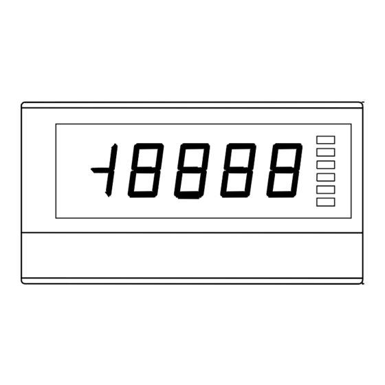
Instruction Manual for MODEL A9□11-0□,A9□12-0□
Instruction Manual for A9000 Series
A9□11-0□ for DC Voltage measurement
A9□12-0□ for DC Current measurement
CAUTION
(1) Applying a voltage or current exceeding its maximum permissible value may cause the
unit to be damaged.
(2) Always use the unit within the specified voltage range: otherwise, it may cause a fire,
electric shock or personal/equipment damage.
(3) For the purpose of functional improvement, the information written herein may be
changed without prior notice.
(4) Information contained herein is considered accurate to the best of our knowledge.
If you have any question or comment on the information, please contact us or our
distributor.
(5) Read this manual carefully and thoroughly before starting to operate the unit,
and keep the manual available for future reference.
1. Before Using the Unit
Thank you for purchasing our A9000 Series Digital Panelmeter. Please
make sure that the operator who uses the panelmeter keeps the manual
on hand. Also, the meter should be checked upon receipt for damage
that might have occurred while in transit. Should the product be
damaged or any accessory be missing, notify your sales representative
or our sales office directly.
1.1. Model and Suffix Code Configuration
The model and suffix code of the A9000 series are as shown below.
Check that the product received matches the one you selected when
ordering.
A
9
□ 1
□
-
0
□
Power
1
100-240V AC
3
5-12V DC
supply :
4
12-24V DC
Display
:
1
Single
Input
:
1
DC voltage
2
DC current
4
AC voltage (true RMS)
5
AC current (true RMS)
6
AC large current (true RMS)
B
Precess signal
C
Temparature sensor
(thermocouple sensor)
D
Temparature sensor
(resistance tempararure detector)
E
DC large voltage(15range)
F
AC large voltage(15range, true RMS)
Comparative
output :
0
(None)
1
(None)+external control inputs
Output
:
2
BCD (TTL)+external control inputs
3
BCD(Open collector)+external control inputs
*Every model is provided with external control inputs.
1.2.
Checking the Accessories
The A9000 series accessories include one copy of this instruction
manual, one unit label and a connector for BCD outputs / external
control inputs.
2.
Mounting Method
2.1.
Panel Cutout Size
Panel cutout size for mounting the A9000 series digital panelmeter is as
+ 0 . 8
92
shown below:
- 0
Digital Panelmeter
(Unit: mm)
*Recommended panel thickness:
MIN 120
WATANABE ELECTRIC INDUSTRY CO., LTD.
2.2 External Dimensions
66.5
53
2.3 How to Mount the Unit on the Panel
(1)After removing the mounting bands, insert
the main unit into a opening in a panel from
the front side of the panel.
Panel (front side)
CAUTION
(1) Do not install the unit where it is exposed to dust, particles, chemicals harmful to
electric components, corrosive gases, etc.
(2) When this unit is installed inside other equipment, pay attention to the heat radiation
and keep the heat inside the equipment 50°C or below.
(3) Exercise care so that the product is not subject to vibrations or shocks.
3. Terminals and Connections
BCD output / External control input connector
Signal input terminals
Lower Terminals
① ② ③ ④ ⑤ ⑥
①:Input terminal HI (+ input terminal of 11 or 12, 22 or 23 -range )
②:Input terminal HI (+ input terminal of 13 or 14, 24 or 25 -range )
③:Input terminal LO (- input terminal )
* Selecting input range can not be done only by connecting input signal
to a suitable terminal. Please set the RANG parameter in condition data.
See "4.6.(8) Setting condition data".
* Make input signal wires as short as possible and keep them away from
other signal wires.
* Use two-core shielded cables in locations with a lot of external noise
and connect the external sheaths to the LO side of the signal source at
one point.
* If harmonic noise is superimposed on an input signal, insert a low-pass
filter in the input. However, care must be exercised depending on the
usage conditions because a delay in response time is caused in time
constant.
④⑤⑥:NC terminals
*Do not connect anything to the NC terminals.
⑦:Power terminal (In case of DC POWER : 0 V)
⑧:Power terminal (In case of DC POWER : +V)
*This panelmeter has no power switch. Connecting it to a power source
causes it to be operable immediately.
0.8 to 5 mm
91.5
8.9
7.8
8.7
96
(2)Attach the mounting bands to main unit
from the rear side of the panel for fixing.
Panel (rear side)
Power input terminals
suitable solder less terminals
5.8mm or less 5.8mm or less
⑦ ⑧
1/8
mounting band
2015.12
UX-34076k
Advertisement
Table of Contents

Related Manuals for WATANABE A9000 Series


Summary of Contents for WATANABE A9000 Series
- Page 1 1.1. Model and Suffix Code Configuration (3) Exercise care so that the product is not subject to vibrations or shocks. The model and suffix code of the A9000 series are as shown below. Check that the product received matches the one you selected when ordering.
-
Page 2: Parameter Settings
Instruction Manual for MODEL A9□11-0□,A9□12-0□ 4.Parameter Settings Upper terminals (without BCD outputs) 4.1 Components and Functions ※ Before setting parameters, remove the front panel by inserting a flat-blade screwdriver into the ditch under the front panel. ① ⑥ ② ③ ④... - Page 3 Instruction Manual for MODEL A9□11-0□,A9□12-0□ Setting Condition Data 4.2 Numeric and Character Indications Condition data is a group of parameters for setting up basic actions such Indications on the main display and characters correspond to them are as a protect level, measurement range, and each control’s operation as below: type.
- Page 4 Instruction Manual for MODEL A9□11-0□,A9□12-0□ 4.7 Setting Scaling Data Scaling data is a group of parameters relating to measurements such as scaling or decimal points. (18) Set up digital limiter type using the Increment key. CUT: Holds display indication at a digital limiter value. OVER: Displays overrange if an input or display value Measuring operation...
-
Page 5: Monitoring Mode
5.2 Monitoring Mode To use the linearize function, carry out this linearize data setup first and The A9000 series panelmeter can display the maximum value, minimum then set the linearize function for activation in the condition data. The value, the difference between them (maximum value - minimum value), linearize function works only after that. -
Page 6: External Control Function
Instruction Manual for MODEL A9□11-0□,A9□12-0□ 5.3 Tracking Zero 7. Specifications The tracking zero is a function for automatically digitally correcting the ■Input Specifications ●DC voltage measurements 23℃±5℃,35 to 85% movement of the zero point inside. This function starts to work at the Range Measurement Input Display... - Page 7 Instruction Manual for MODEL A9□11-0□,A9□12-0□ 8. List of Paremeters 8.1 Condition data Menu Parameter Default value Protect Settable Selections / Ranges Function / Remarks level (*1) Protect Level PL0/PL1/PL2/PL3 Selects the protect level for preventing incorrect operation. The higher the protect level, the more limitations are imposed on a set parameter.
-
Page 8: Error Messages
(1) year warranty period of the meter. 6-16-19, Jingumae, Shibuya-ku, Tokyo 150-0001, Japan 6-16-19, Jingumae, Shibuya-ku, Tokyo 150-0001, Japan WATANABE ELECTRIC INDUSTRY CO., LTD. Phone: (81)3-3400-6140 Phone: (81)3-3400-6141 WATANABE ELECTRIC INDUSTRY CO., LTD.
Need help?
Do you have a question about the A9000 Series and is the answer not in the manual?
Questions and answers