Table of Contents
Advertisement
Instruction Manual for A5000 Series
MODEL A5000 SERIES
INSTRUCTION MANUAL
Caution
!
(1) Do not apply a voltage or current exceeding the maximum allowable
value; otherwise, it may damage the equipment.
(2) Use a power voltage within the operation range; otherwise, it may result
in a fire, electrical shock, or malfunction.
(3) The contents of this manual are subject to change without notice.
(4)
Although the contents of this manual have been prepared with extra
care, if you have any questions, or find errors or missing information,
contact the sales agent from which you purchased the product or
Watanabe Electric Industry Co.,Ltd.
(5)
After reading this manual thoroughly, keep it in a convenient place for
future reference.
(6)
The mark on a label shows the measurement tail range of the input
specification of 8.1. clause.
1.Before Using the Product
Thank you for purchasing the A5000 series. This manual should be passed on to
the person who operates the product. Examine the product for damage caused by
transportation or any other defects. If you find any damage or defects, contact the
sales agent from which you purchased the product or Watanabe
Industry Co., Ltd.
1.1.Model Codes
The model lineup of the A5000 series is shown below. Check that the model
code and specifications of your product match those you specified when
ordering.
A 5 X X X - X X
Power unit
1: 100 to 240 V AC ±10%
2: 9 to 60 V DC
Display unit
1: Single display
2: Multi display
Output unit
0: None
1: Comparison
2: Analog
3: RS-232C
4: RS-485
5: Comparison and analog
6: Comparison, analog, and RS-232C
7: Comparison, analog, and RS-485
Electric
WATANABE ELECTRIC INDUSTRY CO., LTD.
A 5 X X X - X X
Input unit
01: DC voltage measuring unit
(range 11: ±99.99 mV)
02: DC voltage measuring unit
(range 12: ±999.9 mV ; range 13: ±9.999 V)
(range 14:±99.99 V ; range 15: ±600 V)
03: DC current measuring unit
(range 23: ±9.999 mA; range 24: ±99.99 mA)
(range 25: ±999.9 mA)
04: AC voltage measuring unit (average rms)
(range 11: 99.99 mV; range 12: 999.9 mV)
(range 13: 9.999 V)
05: AC voltage measuring unit (average rms)
(range 14: 99.99 V; range 15: 600 V)
06: AC voltage measuring unit (true rms)
(range 11: 99.99 mV; range 12: 999.9 mV)
(range 13: 9.999 V)
07: AC voltage measuring unit (true rms)
(range 14: 99.99 V; range 15: 600 V)
08: AC current measuring unit (average rms)
(range 23: 9.999 mA; range 24: 99.99 mA)
(range 25: 999.9 mA)
09: AC current measuring unit (average rms)
(range 26: 5 A)
10: AC current measuring unit (true rms)
(range 23: 9.999 mA; range 24: 99.99 mA)
(range 25: 999.9 mA)
11: AC current measuring unit (true rms)
(range 26: 5 A)
12: Resistance measuring unit
13: Temperature measuring unit (TC)
14: Temperature measuring unit (RTD)
15: Frequency measuring unit
(inputs: open collector, logic, and magnet)
16: Frequency measuring unit(input: 50 to 500 Vrms)
17: Strain gauze input unit (load cell)
18: Process signal measuring unit (4 to 20 mA or 1 to 5 V)
2.Mounting the Product
2.1.Dimensions for Cutting Panel
Cut the panel for mounting according to the following dimensions.
+0.8
92
-0
120 mm min.
2.2.Mounting the Product to the Panel
To mount the A5000 to the panel, remove its fittings and insert it through the
hole in the front of the panel. From the back of the panel, fix the product to the
panel with the fittings.
1/12
UU-33554t
2015.12
Advertisement
Table of Contents

Related Manuals for WATANABE A5000 Series


Summary of Contents for WATANABE A5000 Series
- Page 1 12: Resistance measuring unit 13: Temperature measuring unit (TC) Thank you for purchasing the A5000 series. This manual should be passed on to 14: Temperature measuring unit (RTD) the person who operates the product. Examine the product for damage caused by 15: Frequency measuring unit transportation or any other defects.
-
Page 2: Terminal Arrangement
Instruction Manual for A5000 Series 2/12 3.3.3. DC Current Measuring Unit Caution Name Description (1) Mount the product to a panel that is strong enough to hold the product. Positive input terminal for range 23 If the panel is not strong enough or the product is not fixed tightly, it (±9.999 mA) -
Page 3: Components And Their Functions
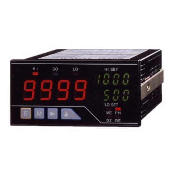
+15V Power output for sensor (positive) Power output for sensor (negative) The front panel design of the A5000 series of unit meters differs depending on the Common terminal (grounding terminal for display unit selected. The names and functions of each unit are as shown below. -
Page 4: Parameter Setup
Instruction Manual for A5000 Series 4/12 Pressing the Mode and Enter keys Pressing the Shift and Mode keys together changes to the shift function together changes to the parameter Selects the item to be set. setup mode. setting mode. Holding down the Shift key for about... - Page 5 Instruction Manual for A5000 Series 5/12 5.2. Moving to the Parameter Setup Mode Calibration data Measurement Shift data Condition data Comparator data Scaling data Linearization data Pressing the ENTER key saves the data and returns to the measurement mode. (Data are backed up with EEPROM even when the power is turned off.) 5.3.
- Page 6 Instruction Manual for A5000 Series 6/12 5.4. Information on Each Parameter 5.4.2 Method of Setting Comparator Data This section explains comparator data and shows a typical example of setting Default Indication Name Setup options value the HI side judgment value. The same method applies to all other parameters.
- Page 7 Instruction Manual for A5000 Series 7/12 5.4.4 Method of Setting Calibration Data Multi-display unit Single display unit 5.4.4.1 Actual Load Calibration Actual load calibration means that calibration is carried out by applying (1) Press the Mode and Enter keys together during measurement.
-
Page 8: Output Function
7.1 Comparison Output Function (1) Press the Mode key and the Enter key during The A5000 series of unit meters is designed so that the two judgment values HI measurement. and LO can be set for the measured (indicated) value to provide the results of judgment as relay contact output. - Page 9 Instruction Manual for A5000 Series 9/12 8.1.4 AC Voltage Measuring Unit (average value detection: ranges 8.1.9 AC Current Measuring Unit (average value detection: range 11 to 13) Maximum Maximum Measurement Highest Input Measurement Highest Input Range Indication permissible Accuracy Range...
-
Page 10: Common Specifications
Instruction Manual for A5000 Series 10/12 Common Specifications 8.1.14 Temperature Measuring Unit (RTD) Input Highest Display : 7-segment LED display (character height : 14.2 mm on main Range Indication Accuracy sensor resolution display and 8 mm on sub-display) PT100Ω -100.0 to 199.9℃... -
Page 11: External Dimensions
Watanabe Electric Industry Co., Ltd. shall be remedied at no cost. Line length Up to 500m (total) In EN/IEC conformity, it is under 30m. -
Page 12: Setting Table
Instruction Manual for A5000 Series 12/12 Setting table Default Default Indication Name value Indication Name value Condition data Scaling data Peak hold setup Full scale Indication value setup RANG Measurement range setup Full scale input value setup Number of averaging... -
Page 13: Specifications
A5000 Series Communication Functions A5000 Series Communication Functions User’s Manual 1. Overview This manual explains the specifications of the communication functions provided by the A5000 series of digital panelmeters. It also explains how to handle the A5000 series. 2. Specifications RS-232C... - Page 14 User’s Manual A5000 Series Communication Functions 3.3. Example of RS-485 Connection If the panelmeter is positioned to be an end station as the result of an RS-485 connection, set the terminator to ON by using the selector socket in the A5000 output unit.
-
Page 15: Communication Commands
User’s Manual A5000 Series Communication Functions 5.3. BCC Checksum As a means of error detection, a block check character (BCC) checksum is added to the RS-485 communication function of the A5000 panelmeter. See the following illustrations for details on the transmission and reception formats (which are as illustrated in the table of communication commands in Section6 for the RS-232C communication function). - Page 16 User’s Manual A5000 Series Communication Functions Function 9 10 11 12 13 14 15 16 17 18 19 20 21 22 23 9 10 11 12 13 14 15 16 17 18 19 20 Char. Length Char. Length Peak hold remote control response...
- Page 17 User’s Manual A5000 Series Communication Functions Function 9 10 11 12 13 14 15 16 17 18 19 20 21 22 23 Char. Length 9 10 11 12 13 14 15 16 17 18 19 20 Char. Length Range response (except for...
- Page 18 User’s Manual A5000 Series Communication Functions Function 9 10 11 12 13 14 15 16 17 18 19 20 21 22 23 9 10 11 12 13 14 15 16 17 18 19 20 Char. Length Char. Length Digital zero backup status response...
- Page 19 User’s Manual A5000 Series Communication Functions Function 9 10 11 12 13 14 15 16 17 18 19 20 21 22 23 9 10 11 12 13 14 15 16 17 18 19 20 Char. Length Char. Length Scaling data response...
- Page 20 User’s Manual A5000 Series Communication Functions Function 9 10 11 12 13 14 15 16 17 18 19 20 21 22 23 Char. Length 9 10 11 12 13 14 15 16 17 18 19 20 Char. Length Calibration data response...
Need help?
Do you have a question about the A5000 Series and is the answer not in the manual?
Questions and answers