Table of Contents
Advertisement
Quick Links
Advertisement
Table of Contents

Related Manuals for Emerson FCLi-56


Summary of Contents for Emerson FCLi-56
- Page 1 Instruction Manual PN 51-FCLi-56 rev.C June 2013 FCLi with 56 Analyzer...
- Page 2 EN50081-2. Emerson Process Management 2400 Barranca Parkway Irvine, CA 92606 USA Tel: (949) 757-8500 Fax: (949) 474-7250 http://www.rosemountanalytical.com...
- Page 3 QUICK START GUIDE FOR FCLi ANALYZER 1. Refer to Section 2.0 for installation instructions and Section 3.0 for wiring instructions. 2. Once connections are secure and verified, apply power to the analyzer. 3. When the analyzer is powered up for the first time Quick Start screens appear. 4.
- Page 4 About This Document This manual contains instructions for installation and operation of the FCLi-56 The following list provides notes concerning all revisions of this document. Rev. Level Date Notes 7/11 This is the initial release of the product manual. The manual has been reformatted to reflect the Emerson documentation style and updated to reflect any changes in the product offering.
-
Page 5: Table Of Contents
MODEL FCLI-56 TABLE OF CONTENTS FCLi-56 TABLE OF CONTENTS Section Title Page DESCRIPTION AND SPECIFICATIONS ..............Applications and Features ..................Specifications ......................Ordering Information ....................INSTALLATION ....................... Unpacking and Inspection..................Installation........................ WIRING........................Preparing Conduit Openings..................Power, Alarm, Output, and Sensor Connections ............. - Page 6 MODEL FCLi-56 TABLE OF CONTENTS TABLE OF CONTENTS CONT’D Section Title Page DIGITAL COMMUNICATIONS ................MAINTENANCE ...................... Analyzer ........................Chlorine Sensor ....................... pH Sensor ........................ Constant Head Flow Controller................TROUBLESHOOTING ................... Overview ........................Using the Diagnostic Feature................... Troubleshooting When a Fault Message is Showing ..........
- Page 7 MODEL FCLi-56 TABLE OF CONTENTS LIST OF TABLES CONT’D 9.6.1 Calibration Error During Two-Point Calibration ............Troubleshooting When No Error Message is Showing - General......9.9.2 Simulating pH Input ....................9.10 Simulating Inputs Temperature................. LIST OF FIGURES Number Title Page Chlorine Sensor Parts ....................
- Page 8 THIS PAGE LEFT BLANK INTENTIONALLY...
-
Page 9: Description And Specifications
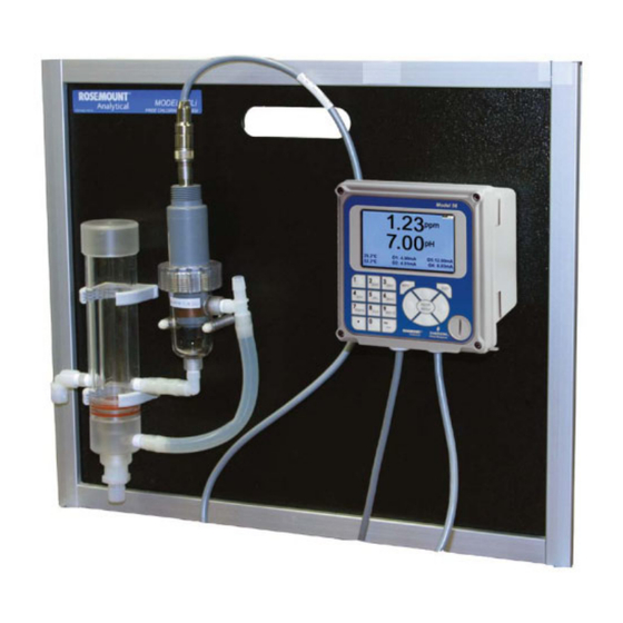
Model FCLi-56 SECTION 1.0 DESCRIPTION AND SPECIFICATIONS SECTION 1.0. DESCRIPTION AND SPECIFICATIONS • COMPLETE SYSTEM INCLUDES sensor, connecting cable, analyzer, and flow controller • SENSOR RESPONSE IS PRACTICALLY INDEPENDENT of pH between pH 6 and 10 • NO REAGENTS • NO AUXILIARY pH ELECTRODE •... -
Page 10: Specifications
MODEL FCLi-56 SECTION 1.0 DESCRIPTION AND SPECIFICATIONS 1.2 SPECIFICATIONS — GENERAL SPECIFICATIONS — ANALYZER Case: Polycarbonate Sample requirements: Display: Full color LCD, 3.75 x 2.20 in. (95 x 56 mm); Pressure: 3 to 65 psig (122 to 549 kPa abs) display can be customized by the user. -
Page 11: Ordering Information
MODEL FCLi-56 SECTION 1.0 DESCRIPTION AND SPECIFICATIONS 1.3 ORDERING INFORMATION Model FCLi Free Chlorine Measuring System. The FCLi is a complete system for the determination of free chlorine in aqueous samples. It consists of the sensor(s), analyzer, and constant head flow controller. All compo- nents are mounted on a backplate. - Page 12 MODEL FCLi-56 SECTION 1.0 DESCRIPTION AND SPECIFICATIONS...
-
Page 13: Installation
MODEL FCLi-56 SECTION 2.0 INSTALLATION SECTION 2.0. INSTALLATION 2.1 UNPACKING AND INSPECTION Inspect the shipping container. If it is damaged, contact the shipper immediately for instructions. Save the box. If there is no apparent damage, unpack the container. Be sure all items shown on the packing list are present. If items are missing, notify Rosemount Analytical immediately. -
Page 14: Installation
MODEL FCLi-56 SECTION 2.0 INSTALLATION 2.2 INSTALLATION 2.2.1 General Information 1. Although the system is suitable for outdoor use, do not install it in direct sunlight or in areas of extreme temperature. CAUTION The FCLi free-chlorine system is NOT suitable for use in hazardous areas. -
Page 15: Chlorine Sensor Parts
MODEL FCLi-56 SECTION 2.0 INSTALLATION fill plug membrane o-ring assembly cable auxiliary membrane electrode retainer cap FIGURE 2-1. Chlorine Sensor Parts 2. If you are using a pH sensor, remove the protective cap on the sensor. 3. Install the sensors in the flow cells as shown in Figures 2.2 and 2.3. For Model FCLi-02-241, the pH sensor must be installed as shown in Figure 2.3. - Page 16 MODEL FCLi-1056 SECTION 2.0 INSTALLATION INCH MILLIMETER CHLORINE SENSOR CHECK VALVE INLET DRAIN FIGURE 2-2. Model FCLi-01-220 INCH MILLIMETER CHLORINE SENSOR pH SENSOR CHECK VALVE INLET DRAIN FIGURE 2-3. Model FCLi-02-221...
-
Page 17: Wiring
MODEL FCL–56 SECTION 3.0 WIRING SECTION 3.0. WIRING 3.1 POWER, ALARM, AND OUTPUT WIRING WARNING RISK OF ELECTRICAL SHOCK Electrical installation must be in accordance with the National Electrical Code (ANSI/NFPA-70) and/or any other applicable national or local codes. 3.1.1 Power Wire AC mains power to the power supply board, which is mounted vertically on the left hand side of the analyzer enclosure. -
Page 18: Alarm Relay Connections
MODEL FCL–56 SECTION 3.0 WIRING 3.1.3 Alarm wiring. WARNING Exposure to some chemicals may degrade the sealing properties used in the following devices: Zettler Relays (K1-K4) PN AZ8-1CH12DSEA The alarm relay terminal strip is located just above the power connector on the power supply board. See Figure 3-2. -
Page 19: Wiring Diagram For Free Chlorine Sensor
MODEL FCL–56 SECTION 3.0 WIRING WHITE Figure 3-3. Wiring Diagram Figure 3-4. Wiring Diagram for Free Chlorine Sensor for 399VP-09 pH Sensor Figure 3-5. Wiring Diagram Figure 3-6. Wiring Diagram for 3900VP-10 pH sensor (gray cable) for 3900VP-10 pH sensor (blue cable) - Page 20 MODEL FCL–56 This page left blank intentionally...
-
Page 21: Display And Operation
MODEL FCL–56 SECTION 4.0 DISPLAY AND OPERATION SECTION 4.0 DISPLAY AND OPERATION 4.1. MAIN DISPLAY The analyzer has a four line display. See Figure 4-1. The display can be customized to meet user requirements. See Section 4.5. Fault or warning messages, if appropriate, appear at the bottom of the screen. See Section 11.1. O3: 12.00 mA T1: 25.0 C O1: 12.00 mA... - Page 22 MODEL FCL–56 SECTION 4.0 DISPLAY AND OPERATION 4.3 OPERATION The operation of the Model 56 can best be understood from the following example. 1. With the main display showing (Figure 4-1), press the ENTER/MENU key. S1: 1.00 ppm 25.0 C S2: 7.00 pH 25.0 C The main menu, shown at left, will appear.
- Page 23 MODEL FCL–56 SECTION 4.0 DISPLAY AND OPERATION 7. The default dampening value is 0 seconds. To change the value, press S1: 1.00 ppm 25.0 C S2: 7.00 pH 25.0 C ENTER/MENU. The dark blue back-lighting will disappear indicating that Outputs Relays Measure Temperature Security a number can be entered.
- Page 24 MODEL FCL–56 SECTION 4.0 DISPLAY AND OPERATION 4.4 HOLD 4.4.1 Purpose To prevent unwanted alarms and improper operation of control systems or dosing pumps, place the alarm relays and outputs assigned to the sensor in hold before removing the sensor for maintenance. Hold is also useful if calibration, for example, buffering a pH sensor, will cause an out of limits condition.
- Page 25 MODEL FCL–56 SECTION 4.0 DISPLAY AND OPERATION 1. With the main display showing, press ENTER/MENU. The main menu will S1: 1.00 ppm 25.0 C S2: 7.00 pH 25.0 C Graphics Display setup Tag Language Warning appear. Choose Display Setup. The screen shown at left appears. View graph Upper graph Lower graph...
-
Page 26: Security
MODEL FCL–56 SECTION 4.0 DISPLAY AND OPERATION 4.6 SECURITY 4.6.1 How the Security Code Works Security codes prevent accidental or unwanted changes to program settings or calibrations. There are three levels of security. a. A user can view the main display and diagnostic screens only. b. -
Page 27: Programming The Analyzer
MODEL FCL–56 SECTION 5.0 PROGRAMMING THE ANALYZER SECTION 5.0 PROGRAMMING THE ANALYZER 5.1 ENTERING THE PROGRAM MENUS 1. With the main display showing, press ENTER/MENU to display the main S1: 1.00 ppm 25.0 C S2: 7.00 pH 25.0 C menu. Move the cursor to Program and press ENTER/MENU. Calibrate Data storage and retrieval Program... - Page 28 MODEL FCL–56 SECTION 5.0 PROGRAMMING THE ANALYZER 5.2.2. Settings Move the cursor to the appropriate control box and make the desired setting. For more information about the con- trol box the cursor is on press INFO. To close the information screen, press any key. 5.3 RELAYS 5.3.1 Menu Tree Figure 5-2 is the Relays menu tree.
- Page 29 MODEL FCL–56 SECTION 5.0 PROGRAMMING THE ANALYZER 5.3.2. Settings 1. A large number of relay actions are available in the Model 56. For more S1: 1.00 ppm 25.0 C S2: 7.00 pH 25.0 C information about a relay action, move the cursor the Explanation of relay Outputs Relays Measure Temperature Security actions button and press ENTER/MENU.
- Page 30 MODEL FCL–56 SECTION 5.0 PROGRAMMING THE ANALYZER 5.4 MEASUREMENT 5.4.1 Menu Tree Figure 5-3 is the Measurements menu tree. Measurement Sensor 1 or 2 Sensor 1 (Cl) Sensor 2 (pH) Measurement Pre-amplifier location Units Filter Resolution Reference impedance pH correction* Wiring Filter Resolution...
- Page 31 MODEL FCL–56 SECTION 5.0 PROGRAMMING THE ANALYZER 5.5.2. Settings Move the cursor to the appropriate control box and make the desired setting. For more information about the con- trol the cursor is on press INFO. To close the information screen, press any key. 5.6 pH DIAGNOSTIC SETUP 5.6.1 Menu Tree Figure 5-5 is the pH diagnostic setup menu tree.
- Page 32 MODEL FCL–56 This page left blank intentionally...
-
Page 33: Calibration
MODEL FCL–56 SECTION 6.0 CALIBRATION SECTION 6.0 CALIBRATION 6.1 INTRODUCTION The calibrate menu allows the user to do the following: 1. Calibrate the RTD (temperature sensing element) in the chlorine and pH sensors. 2. Calibrate the chlorine sensor. 3. Calibrate the pH sensor. Four methods are available. a. - Page 34 MODEL FCL–56 SECTION 6.0 CALIBRATION 6.4 CALIBRATING THE FREE CHLORINE SENSOR 1. Choosing sensor 1 (free chlorine) in section 6.2 causes the screen shown S1: 1.00 ppm 25.0 C S2: 7.00 pH 25.0 C at left to appear. There are two steps to calibrating a free chlorine sensor, Why is calibration necessary? To find out press INFO.
- Page 35 MODEL FCL–56 SECTION 6.0 CALIBRATION 6.5 CALIBRATING THE pH SENSOR 1. Choosing sensor 2 (pH) in section 6.2 causes the screen shown at left to S1: 1.00 ppm 25.0 C S2: 7.00 pH 25.0 C appear. There are five possible ways to calibrate the pH sensor. Select Why is calibration necessary? To find out press INFO.
- Page 36 MODEL FCL–56 This page left blank intentionally...
-
Page 37: Digital Communications
MODEL FCL–56 SECTION 7.0 DIGITAL COMMUNICATIONS SECTION 7.0 DIGITAL COMMUNICATIONS The Model 56 analyzer supplied with the FCL has HART communications as a standard feature. For more information refer to the Model 56 HART Addendum Manual. - Page 38 MODEL FCL–56 This page left blank intentionally...
- Page 39 MODEL FCL–56 SECTION 8.0 DATA AND EVENT LOGGING AND RETRIEVAL SECTION 8.0 DATA AND EVENT LOGGING AND RETRIEVAL 8.1. OVERVIEW Data and event logging is a standard feature in the Model 56 analyzer. However, the feature must be enabled. When data/event logging is enabled, the Model 56 analyzer will automatically store the following events with date and time stamp: faults, warnings, calibration data, calibration results (pass or fail), power on/off cycles, hold on/off, and new sensor board detected.
- Page 40 MODEL FCL–56 SECTION 8.0 DATA AND EVENT LOGGING AND RETRIEVAL 8.3. DOWNLOADING DATA AND EVENTS To download data or events, move the cursor to the download tab and press ENTER/MENU. Unscrew the USB port cover in the lower right hand corner of the front panel and insert a USB flash drive in the port. Press the appropriate button to download data or events.
- Page 41 MODEL FCL–56 SECTION 9.0 GRAPHICAL DISPLAY SECTION 9.0 GRAPHICAL DISPLAY 9.1. OVERVIEW The Model 56 has a dual graphical display. Each graph can be configured to meet user requirements, although the time axis on both graphs must be the same. The time scale can be one hour, one day, seven days, or 30 days. 9.2.
- Page 42 MODEL FCL–56 This page left blank intentionally...
-
Page 43: Maintenance
MODEL FCLi-56 SECTION 8.0 MAINTENANCE SECTION 10.0 MAINTENANCE 10.1 ANALYZER The analyzer used with the FCLi needs little routine maintenance. Clean the analyzer case and front panel by wiping with a clean soft cloth dampened with water ONLY. Do not use solvents, like alcohol, that might cause a buildup of static charge. -
Page 44: Chlorine Sensor
SECTION 8.0 MAINTENANCE 10.2 CHLORINE SENSOR 10.2.1 General. When used in clean water, the 498CL-01 chlorine sensor requires little maintenance. Generally, the sensor needs maintenance when the response becomes sluggish or noisy or when readings drift following calibration. For a sen- sor used in potable water, expect to clean the membrane every month and replace the membrane and electrolyte slurry every three months. -
Page 45: Spare Parts
MODEL FCLi-56 SECTION 8.0 MAINTENANCE fill plug membrane o-ring assembly auxiliary membrane electrode retainer cap FIGURE 10-1. Chlorine Sensor Parts SPARE PARTS 33970-00 Fill Plug 33521-03 Membrane retainer cap 23501-10 pH-independent free chlorine membrane assembly, includes one membrane assembly and O-ring... -
Page 46: Ph Sensor
MODEL FCLi-56 SECTION 8.0 MAINTENANCE 2. If the sensor was powered up during storage, the cathode is probably coated with metallic copper. Disconnect the sensor from the analyzer. Remove the membrane and clean out the fill slurry. Immerse the mesh cathode in 10% nitric acid solution (10 mL of concentrated nitric acid in 90 mL of water) for about five minutes. -
Page 47: Replacement Parts For Constant Head Flow Controller Assembly (Model Fcli-01)
MODEL FCLi-56 SECTION 8.0 MAINTENANCE TABLE 10-2. Replacement parts for constant head flow controller assembly (Model FCLi-01) Location in Shipping Figure 10-2 Description Weight 24039-00 Flow cell for chlorine sensor with bubble shedding nozzle 1 lb/0.5 kg 24040-00 O-ring kit, two 2-222 and one 2-024 silicone O-rings, 1 lb/0.5 kg... -
Page 48: Replacement Parts For The Flow Controller Assembly Used In Model Fcli-02
MODEL FCLi-56 SECTION 8.0 MAINTENANCE TABLE 10-3. Replacement parts for constant head flow controller assembly (Model FCLi-02) Location in Shipping Figure 8-3 Description Weight 24039-00 Flow cell for chlorine sensor with bubble shedding nozzle 1 lb/0.5 kg 24039-01 Flow cell for pH sensor 1 lb/0.5 kg... -
Page 49: Troubleshooting
MODEL FCL–56 SECTION 11.0 TROUBLESHOOTING SECTION 11.0 TROUBLESHOOTING 11.1 OVERVIEW The analyzer continuously monitors itself and the sensor(s) for problems. When the analyzer identifies a problem, the word warning or fault appears intermittently at the bottom of the display. To read the fault or warning message and troubleshooting information, press INFO. - Page 50 MODEL FCL–56 SECTION 11.0 TROUBLESHOOTING 11.4 TROUBLESHOOTING CALIBRATION PROBLEMS If a calibration attempt results in an error or a likely error, the analyzer will display the appropriate warning screen. For troubleshooting suggestions, press the INFO key. 11.5 OTHER TROUBLESHOOTING — CHLORINE Although calibration troubleshooting information is available in the analyzer by pressing the INFO key, troubleshooting information for process measurement problems is not.
- Page 51 MODEL FCL–56 SECTION 11.0 TROUBLESHOOTING 11.5.3 Sensor does not respond to changes in chlorine level. 1. Is the grab sample test accurate? Is the grab sample representative of the sample flowing to the sensor? 2. Is sample flowing past the sensor? Be sure the liquid level in the constant head sampler is level with the central overflow tube and that excess sample is flowing down the tube.
-
Page 52: Sensor Wiring
MODEL FCL–56 SECTION 11.0 TROUBLESHOOTING 11.6.2 Buffer Calibration Is Acceptable, Process pH Is Slightly Different from Expected Value. Differences between pH readings made with an on-line instrument and a laboratory or portable instrument are normal. The on-line instrument is subject to process variables, for example ground potentials, stray voltages, and orientation effects that may not affect the laboratory or portable instrument. -
Page 53: Simulating Inputs - Chlorine
MODEL FCL–56 SECTION 11.0 TROUBLESHOOTING 11.7 OTHER TROUBLESHOOTING — GENERAL Problem See Section Current output is too low 11.7.1 Alarm relays do not operate properly 11.7.2 11.7.1 Current Output Is Too Low. Load resistance is too high. Maximum is 550Ω. 11.7.2 Alarm Relays Do Not Operate Properly 1. -
Page 54: Simulating Inputs - Ph
MODEL FCL–56 SECTION 11.0 TROUBLESHOOTING 11.9 SIMULATING INPUTS — pH 11.9.1 General This section describes how to simulate a pH input into the analyzer. To simulate a pH measurement, connect a standard millivolt source to the analyzer. If the analyzer is working properly, it will accurately measure the input voltage and convert it to pH. -
Page 55: Simulating Inputs Temperature
MODEL FCL–56 SECTION 11.0 TROUBLESHOOTING 11.10 SIMULATING INPUTS — TEMPERATURE 11.10.1 General. The analyzer accepts a Pt100 RTD (for pH and chlorine sensors). The Pt100 RTD is in a three-wire configuration. See Figure 11-2. 11.10.2 Simulating temperature To simulate the temperature input, wire a decade box to the analyzer as shown in Figure 11-3. - Page 56 A Worldwide Network of Sales and Service Emerson Process Management’s field sales offices are your source for more information on the fill line of Rosemount Analytical products. Field sales personnel will work closely with you to supply technical data and application information.
- Page 57 NESS FOR PARTICULAR PURPOSE, OR ANY OTHER MATTER WITH RESPECT TO ANY OF THE GOODS OR SERVICES. RETURN OF MATERIAL Material returned for repair, whether in or out of warranty, should be shipped prepaid to: Emerson Process Management Rosemount Analytical 2400 Barranca Parkway...
- Page 58 ON-LINE ORDERING NOW AVAILABLE ON OUR WEB SITE right now. http://www.rosemountanalytical.com Specifications subject to change wihout notice. Credit Cards for U.S. Purchases Only. Emerson Process Management 2400 Barranca Parkway Irvine, CA 92606 USA Tel: (949) 757-8500 Fax: (949) 474-7250 http://www.rosaemountanalytical.com...
Need help?
Do you have a question about the FCLi-56 and is the answer not in the manual?
Questions and answers