
Related Manuals for SolaX Power X1-Hybrid-LV Series


Summary of Contents for SolaX Power X1-Hybrid-LV Series
- Page 1 X1-Hybrid-LV 3.0 KW / 3.7 KW / 4.0 KW / 4.6 KW/ 5.0 KW / 6.0 KW User Manual Version 1.0 www.solaxpower.com eManual in the QR code or athttp://kb.solaxpower.com/...
- Page 3 No part of this manual may be reproduced, transmitted, transcribed, stored in a retrieval system, or translated into any language or computer language, in any form or by any means without the prior written permission of SolaX Power Technology (Zhejiang) Co., Ltd. Trademarks and other symbol or design (brand name, logo) that distinguishes the products or services offered by SolaX has been trademark protected.
- Page 4 About This Manual Scope of Validity This manual is an integral part of X1-Hybrid-LV series inverter. It describes the transportation, storage, installation, electrical connection, commissioning, maintenance and troubleshooting of the product. Please read it carefully before operating. This manual is valid for the following inverter models: •...
- Page 5 Conventions The symbols that may be found in this manual are defined as follows. Symbol Description Indicates a hazardous situation which, if not avoided, DANGER will result in death or serious injury. Indicates a hazardous situation which, if not avoided, WARNING could result in death or serious injury.
-
Page 6: Table Of Contents
Table of Contents Safety ......................1 1.1 General Safety ........................1 1.2 Safety Instructions of PV, Inverter and Grid ...............1 1.2.1 Safety Instructions of PV ..................2 1.2.2 Safety Instructions of Inverter ................2 1.2.3 Safety Instructions of Utility Grid ..............3 Product Overview ..................4 2.1 Product Introduction ......................4 2.2 Supported Power Grid .....................4 2.3 Appearance .........................5... - Page 7 Unpacking and Inspection ..............25 6.1 Unpacking ..........................25 6.2 Scope of Delivery.......................26 Mechanical Installation ................28 7.1 Dimensions for mounting ....................29 7.2 Installation procedures.....................30 Electrical Connection ................33 8.1 Terminals of Inverter ......................33 8.2 PE Connection ........................35 8.3 AC Connection ........................38 8.4 PV Connection ........................46 8.5 Battery Power Cable Connection .................51 8.5.1 Battery connection ....................51 8.5.2 Battery temperature sensor connection ............56...
- Page 8 12.1 Troubleshooting .........................92 12.2 Maintenance ........................99 12.3 Firmware Upgrade ......................100 12.3.1 Upgrade preparation ...................100 12.3.2 Upgrade steps .......................100 Decommissioning ..................102 13.1 Power off ..........................102 13.2 Disassembling the Inverter ....................103 13.3 Packing the Inverter ......................104 13.4 Disposing of the Inverter ....................104 Technical Data ..................105 14.1 DC Input ..........................105 14.2 AC Input&Output .......................105...
-
Page 9: Safety
Safety General Safety The series inverter has been meticulously designed and thoroughly tested to comply with all relevant state and international safety standards. Nevertheless, like all electrical and electronic equipment, safety precautions must be observed and followed during the installation of the inverter to minimize the risk of personal injury and ensure a safe installation. -
Page 10: Safety Instructions Of Pv
Safety 1.2.1 Safety Instructions of PV DANGER! Potential risk of lethal electrical shock associated with the photovoltaic (PV) system • Exposure to sunlight can result in the generation of high DC voltage by PV modules, which can lead to electric shock causing severe injuries or even death. •... -
Page 11: Safety Instructions Of Utility Grid
Safety WARNING! • During operation, avoid touching any parts of the inverter other than the DC switch and LCD panel (if any). • Never connect or disconnect the AC and DC connector while the inverter is running. • Prior to conducting any maintenance, turn off the AC and DC power and disconnect them from the inverter. -
Page 12: Product Overview
Product Overview Product Introduction The X1-Hybrid-LV series inverter is a high-quality inverter that combines solar inverter, solar charger, AC charger, and emergency power supply (EPS) function with an IP65 degree of protection. The inverter can be used to optimize self-consumption, store energy in batteries for future use, or feed it into the public grid. -
Page 13: Appearance
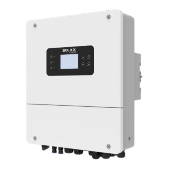
Product Overview TN-C-S Figure 2-3 Supported power grid TN-C-S Appearance LCD panel Nameplate Electrical DC switch connection area Figure 2-4 Apprearance Table 2-1 Desciption of appearance Item Description Nameplate clearly identifies the device type, serial number, specific Nameplate DC / AC parameters, certification, etc. Including screen, indicators and keys. -
Page 14: Dimensions
Product Overview 2.3.1 Dimensions • Dimension of Inverter 201 mm 397 mm Figure 2-5 Dimension of Inverter 2.3.2 Control Panel • Control Panel of Inverter LCD Screen Operating indicator light Battery indicator light Down Error Enter indicator light Figure 2-6 Control Panel of Inverter * Please refer to the actual product for the color of the LCD screen. - Page 15 Product Overview Table 2-3 Definition of indicators of Inverter LED indicator Status Definition The inverter is in grid-connected Solid green operation state or off-grid operation state. The inverter is in the process of grid Green blinking Operating connection or off-grid. The inverter is in a fault or manual Light off shutdown state.
-
Page 16: Symbols On The Label And Inverter
Product Overview Symbols on the Label and Inverter Table 2-4 Description of symbols Symbol Description CE mark. The inverter complies with the requirements of the applicable CE guidelines. TUV certified. UKCA mark. The inverter complies with the requirements of the applicable UKCA guidelines. -
Page 17: Working Principle
The principle design of inverter is shown in the figure below: DC Switch PV1+ GEN_L PV MPPT1 GEN_N DC/DC PV1- EPS_L DC BUS DC/AC EPS_N Filter Filter PV2+ PV MPPT2 Grid_L DC/DC PV2- Grid_N DC SPD AC SPD BAT+ DC/DC Filter BAT- Figure 2-7 Circuit Diagram for X1-Hybrid-LV series inverter... -
Page 18: Application Schemes
Product Overview 2.5.2 Application Schemes The series inverter is a high-quality inverter that combines solar inverter, solar charger, AC charger, and emergency power supply (EPS) function with an IP65 degree of protection. The inverter can be used to optimize self-consumption, store energy in batteries for future use, or feed it into the public grid. - Page 19 Product Overview Diagram B: Neutral line and PE line are combined together, and the emergency load is connected to the EPS port. (For Australia) Battery DC Breaker Inverter PV Module GRID L N PE AC Breaker AC Breaker AC Breaker N-BAR Grid E-BAR...
-
Page 20: Working State
Product Overview Working State The series inverter has Start, On and Off state. Table 2-5 Description of working state State Description Start The inverter is checking for conditions to enter On state. The inverter is working normally. • The inverter is waiting for the conditions to be met in order to enter the Start state. -
Page 21: Backup Mode
Product Overview Only Solar charging: Solar charges the battery, and the load is completely powered by the power grid; Solar then Utility charging: If there is Solar energy, only Solar energy will charge the battery; if there is no solar energy, the power grid will charge the battery; Solar+Utility: Same as 2 (Only Utility charging);... -
Page 22: Time Of Use Mode
Product Overview 2.7.3 Time of use mode This mode is applicable to all countries including Pakistan . Application Scenarios: This mode is more suitable for applications with peak and off-peak electricity price differences. When the electricity price is high, the battery discharges to power the load. When the electricity price is low, the battery is charged from solar or the grid to reach full capacity. -
Page 23: Sbu Mode
Product Overview Note: In this mode, if the priority setting for the battery charging source is as follows: Only Solar Charging: No response, and the normal operation mode described above is followed. Solar then Utility Charging: If solar power is available, the battery is exclusively charged by solar. -
Page 24: Mks Mode
Product Overview 2.7.6 MKS Mode This mode is applicable under Pakistan's safety. Application Scenarios: This mode is suitable for customers who have higher electricity consumption during certain periods of the day and lower consumption at night. When solar power is available, this mode is basically the same as the SBU mode, and the discharge range of the battery is wider than that of the SBU mode. -
Page 25: System Overview
System Overview System Overview Solax Cloud Inverter Home Loads EPS Loads Solar Grid Battery Diesel Grid-tied Smart Loads Generator Inverter Communication Figure 3-1 System overview diagram... - Page 26 Table 3-1 System item description Item Description The series inverter combines solar inverter, solar charger, AC X1-Hybrid-LV series charger and emergency power supply (EPS) function together with (the device covered IP65 degree of protection. The inverter can be used to optimize...
-
Page 27: Transportation And Storage
Transportation and Storage If the inverter is not put into use immediately, the transportation and storage requirements needs to be met: Transportation • Observe the caution signs on the packaging of inverter before transportation. • Pay attenting to the weight of inverter. Be cautious to avoid injury when carrying X1-Hybrid-LV (gross weight: 20 kg). -
Page 28: Preparation Before Installation
Preparation before Installation Selection of Installation Location The installation location selected for the inverter is quite critical in the aspect of the guarantee of machine safety, service life and performance. It has the IP65 ingress protection, which allows it to be installed outdoor. The installation position shall be convenient for wiring connection, operation and maintenance. -
Page 29: Installation Carrier Requirement
Preparation before Installation Sea breeze Inverter 500 m 1000 m Figure 5-1 Recommended installation position Sea breeze Inverter 500 m 1000 m Figure 5-2 Incorrect installation position NOTICE! • For the installation of the whole system, please refer to the specific environment requirement of each unit. -
Page 30: Clearance Requirement
Preparation before Installation 5.1.3 Clearance Requirement The minimum clearance reserved for the connected terminal at the bottom of inverter should be 10 cm. When planning installation space, it is important to simultaneously consider the bending radius of the wires. To guarantee proper heat dissipation and ease of disassembly, the minimum space around the inverter must meet the standards indicated below. -
Page 31: Tools Requirement
Preparation before Installation Tools Requirement Installation tools include but are not limited to the following recommended ones. If necessary, use other auxiliary tools on site. Hammer drill Multimeter Measuring tape Utility knife Flat-head Marker Cross screwdriver screwdriver Allen key Crimping tool for Crimping tool Diagonal pliers Wire stripper... -
Page 32: Additionally Required Materials
Preparation before Installation Additionally Required Materials Table 5-2 Additionally required wires Conductor Required Material Type Cross-section Dedicated PV wire with a voltage PV wire 4 mm² rating of 600 V Communication Network cable CAT5E 0.2 mm² wire 1 Additoinal PE Conventional yellow and green 4 mm²-10 mm²... -
Page 33: Unpacking And Inspection
Unpacking and Inspection Unpacking • The inverter undergoes 100% testing and inspection before shipping from the manufacturing facility. However, transport damage may still occur. Before unpacking the inverter, please check the outer packing materials for damage, such as holes and cracks. •... -
Page 34: Scope Of Delivery
Unpacking and Inspection Scope of Delivery Table 6-1 Packing list Item Description Quantity Inverter 1 pc Wall mounting bracket 1 pc Negative PV connectors 2 pcs Negative PV pin contacts 2 pcs Positive PV connectors 2 pcs Positive PV contacts 2 pcs Expansion tubes 3 pcs... - Page 35 Unpacking and Inspection Item Description Quantity Washers 3 pcs Battery connection terminals 2 pcs Y terminals 9 pcs OT terminal 1 pc M4*12 Screws 4 pcs RJ45 connectors 2 pcs RJ45 terminals 4 pcs Document Battery temperature sensor 1 pc CT (CT cable: 50 cm) 1 pc Tool Wrench...
-
Page 36: Mechanical Installation
Mechanical Installation WARNING! • Only the qualified personnel can perform the mechanical installation following the local standards and requirements. • Check the existing power cables or other piping in the wall to prevent electric shock or other damage. CAUTION! • Always be aware of the weight of the inverter. Personal injuries may result if the inverter is lifted improperly or dropped while being transported or mounted. -
Page 37: Dimensions For Mounting
Mechanical Installation Dimensions for mounting Check the dimensions of the wall mounting bracket before mounting and reserve sufficient space for heat dissipation and installation of the whole system. Figure 7-3 Dimensions 1 (Unit: mm) 198.5 198.5 Ø10 Figure 7-4 Dimensions 2 (Unit: mm) -
Page 38: Installation Procedures
Mechanical Installation Installation procedures Step 1: Align the wall mounting bracket horizontally on the wall and mark the position of the drill holes. Figure 7-5 Marking the holes NOTICE! • Take the height of the battery into account when mounting the wall mounting bracket. - Page 39 Mechanical Installation Step 3: Attach the wall mounting bracket on the wall again. Insert the expansion bolt into the holes and secure the wall bracket to the wall with expansion screws. Figure 7-7 Insert the expansion bolt ST6.0 Figure 7-8 Securing the wall mounting bracket Step 4: Open the anti-static bag and take out the machine.
- Page 40 Mechanical Installation 1.5 ± 0.1 N·m Figure 7-10 Securing the inverter NOTICE! • If the inverter is temperally needed to be placed on the ground, use foam or other protective materials to prevent any damage of inverter.
-
Page 41: Electrical Connection
Electrical Connection DANGER! • Before electrical connection, make sure the DC switch and AC breaker are disconnected. Otherwise, electrical shock may be caused by high voltage, resulting in serious personal injury or death. WARNING! • Only the qualified personnel can perform the electrical connection following the local standards and requirements. - Page 42 Electrical Connection Figure 8-2 Terminals of Inverter (Bottom view 1) Figure 8-3 Terminals of Inverter (Bottom view 2) Table 8-1 Description of terminals Item Description Communication ports Battery input connectors Dry-contact output Grid Generator input Battery power on button DC Switch PV input with two MPPT...
-
Page 43: Pe Connection
Electrical Connection Item Description Waterproof valve BAT+/BAT- USB port for upgrading/External monitoring connection port Overload reset button COM1/COM2/COM3 (for communication connection) Fan (Only for X1-Hybrid-5.0-LV and X1-Hybrid-6.0-LV) PE Connection All non-current carrying metal parts of the equipment and other enclosures in the PV system must be grounded reliably. - Page 44 Electrical Connection NOTICE! • When AC cable ≤16 mm , the earthing conductor should be as thick as the AC cable. . Step 2: Pull the heat-shrink tubing over the PE cable and insert the stripped section into the OT terminal. Figure 8-5 Installing the tubing and OT teriminal Step 3: Crimp it with crimping tool, pull the heat-shrink tubing over the stripped...
- Page 45 Electrical Connection Step 4: Find the ground connection port on the inverter, loosen the PE screw on the inverter with cross screwdriver and screw the ground wire on the inverter with a cross screwdriver. 1.5± 0.1 N·m Figure 8-8 Securing the PE cable...
-
Page 46: Ac Connection
Electrical Connection AC Connection NOTICE! • The series inverter is a single-phase inverter suitable for rated voltages of 220/230/240V and frequencies of 50/60Hz. For more technical requirements, please consult the regulations of the local public grid. • A circuit breaker should be installed between the inverter and the mains, and the load should not be directly connected to the inverter. - Page 47 Electrical Connection WARNING! • Ensure that the EPS load's rated power is within the EPS rated output power range; otherwise, the inverter will report an overload warning. • If an overload occurs, adjust the load power to ensure it is within the EPS rated output power range, and the inverter will automatically return to normal operation.
- Page 48 Electrical Connection Step 2: Use a cross screwdriver to loosen the screws on both sides of the inverter. Remove the lower cover of the inverter. Remove 1.5± 0.1 N·m Figure 8-3 Loosen the screws Figure 8-4 Remove the lower cover Step 3: Remove the plug of Grid, GEN and EPS ports.
- Page 49 Electrical Connection Grid PE L N L N L N PE Figure 8-6 Find the Location Step 5: Pass the previously prepared Grid, GEN and EPS cables through the corresponding screw caps and seals rings. The Grid, GEN, and EPS cables should go through the corresponding Grid, GEN, and EPS ports.
- Page 50 Electrical Connection Figure 8-9 Pass the EPS cable Step 6: Remove the 10 mm insulation layer at the end of the wire. Insert the fork terminals respectively, and make sure that the stripped ends are inserted into the fork terminal, and finally use crimping pliers to press tightly. Figure 8-10 Remove the layer Figure 8-11 Insert and press the terminal Step 7:...
- Page 51 Electrical Connection Figure 8-12 Insert the Grid cable Figure 8-13 Tighten the Grid cable Figure 8-14 Grid cable connected...
- Page 52 Electrical Connection Figure 8-15 Insert the GEN cable Figure 8-16 Tighten the GEN cable Figure 8-17 GEN cable connected...
- Page 53 Electrical Connection Figure 8-18 Insert the EPS cable Figure 8-19 Tighten the EPS cable Figure 8-20 EPS cable connected...
-
Page 54: Pv Connection
Electrical Connection PV Connection The series inverters have two PV inputs. Please select photovoltaic modules with good performance and quality assurance. The open circuit voltage of the module array should be less than the maximum PV input voltage specified by the inverter, and the working voltage should be within the MPPT voltage range. - Page 55 Electrical Connection Requirements for PV connection • The series inverters support the following PV module connection modes. » Method : Multi Inverter Figure 8-21 Striping the PV cable Wiring procedures Step 1: Turn off the DC switch, prepare a 4 mm² PV cable, and find the PV (+) terminal and PV (-) terminal in the package.
- Page 56 Electrical Connection Figure 8-24 Crinping the terminal WARNING! • To mitigate the risk of fire, it is crucial to utilize a dedicated crimping tool specifically designed for PV installations to ensure secure and reliable connections. Step 3: Thread the PV cable through swivel nut and insert the cable into the PV connector until a "Click"...
- Page 57 Electrical Connection Figure 8-27 Unlocking the PV cable Step 4: Use a multimeter to measure the positive and negative voltage of the assembled PV connectors. Make sure the open circuit voltage does not exceed the input limit of 500 V. Figure 8-28 Measuring the voltage of PV connectors NOTICE! •...
-
Page 58: Battery Power Cable Connection
Electrical Connection Click! Figure 8-29 Connecting the PV cable WARNING! • Seal the unused PV terminals with original terminal caps. If all PV terminals are connected, keep the waterproof caps in a safe place. Reinstall it immediately after removing the connectors from terminals. Battery Power Cable Connection 8.5.1 Battery connection... - Page 59 Electrical Connection Non-polar DC MCB Communication line connection Power line connection CAN/RS485 Low voltage lithium battery Figure 8-30 Battery connection diagram Requirments for battery connection • Required battery » The series inverter system can be equipped with low voltage lithium battery and lead acid battery.
- Page 60 Electrical Connection • Please ensure that the BAT power line and BMS communication line are correctly connected when using the low-voltage batteries TP-LR25 and TP-LR36. Check T-BAT LR25 & T-BA LR36 Installation Manual for details. Battery connection steps Step 1: Prepare a 16-25 mm²...
- Page 61 Electrical Connection Figure 8-34 Connecting the battery connector • For battery connection from 3.0 kW to 4.0 kW Step 4: Remove the sealing cover of the plug. Figure 8-35 Remove the sealing cover Step 5: Pass the previously assembled cables through the corresponding swivel nut. Find the battery interface, insert the positive cable into BAT+ port and the negative cable to BAT-port.
- Page 62 Electrical Connection Remove 5.0±0.1 N·m Figure 8-37 Remove the screw Step 7: Use cross screwdriver to tighten the screw. Twist to tighten the swivel nut. 5.0±0.1 N·m Figure 8-38 Tighten the cable • For battery connection from 4.6 kW to 6.0 kW Step 4: Remove the plug.
- Page 63 Electrical Connection 35-50 mm² (Recommend 35 mm² copper wire ) Figure 8-40 Pass and insert the cable Step 6: Find the battery interface, remove the screw. insert the positive cable into BAT+ port and the negative cable to BAT-port. Remove 5.0±0.1 N·m Figure 8-41 Remove the screw Step 7:...
-
Page 64: Battery Temperature Sensor Connection
Electrical Connection • Keep the terminal caps in a safe place if batteries are connected to the inverter. • Reinstall the caps immediately after removing the connectors from terminals. NOTICE! • If only the battery is connected but the PV, GRID, and GEN are not connected, to start the inverter, press and hold the battery power on button until the screen is on. - Page 65 Electrical Connection Figure 8-44 Insert the cable into the BMS port Lead-acid battery Figure 8-45 Attach the terminal...
-
Page 66: Communication Connection
Electrical Connection Communication Connection Figure 8-46 Communication ports Table 8-5 Definition of communication ports Number Description Dry-contact output DRM(optional) Parallel_1 Parallel_2 Meter/CT 8.6.1 CT/meter port connnection The inverter should work with an electric meter or current sensor (CT for short) to monitor household electricity usage. - Page 67 Electrical Connection Figure 8-47 customize the CT cable NOTICE! • The meter or CT must be connected to the inverter; otherwise, the inverter will shut down and trigger a "meter failure" alarm. Smart meters must be authorized by us, third-party, or other companies. Unauthorized meters may be incompatible with the inverter.
- Page 68 Electrical Connection Meter connection diagram The current sensor measures the current on the live wire between the inverter and the public grid. • Meter connection diagram Grid Loads Household Meter Meter 1 Meter 2 Other power generation equipment Figure 8-49 Meter connection diagram NOTICE! •...
- Page 69 Electrical Connection CT/Meter connection steps Step 1: Remove the plug. For Communication connection, you can select any port from COM 1, COM 2 and COM3. Figure 8-50 Remove the plug Step 2: For meter connection, crimp only one RJ45 terminal. For CT connection without RJ45 connector, there is no need to crimp another RJ45 terminal.
- Page 70 Electrical Connection Figure 8-52 Insert one side of the cable into the inverter waterproof distribution box Figure 8-53 Insert the other side of the cable into the waterproof distribution box Step 4 : For CT connection without RJ45 connector, insert one side of the finished cable and the waterproof connectors with RJ45 into the Meter/CT port of the inverter, tighten the waterproof screw and insert the other side of the RJ45 terminal into the CT connection.
- Page 71 Electrical Connection CT connection without RJ45 connector Figure 8-55 Insert the other side of the cable into the CT connection Step 4 : For CT connection with RJ45 connector, connect the A terminal to the Meter/CT port of the inverter, tighten the waterproof screw and connect the B terminal to the RJ45 coupler.
-
Page 72: Bms/Drm/Com Port Connnection
Electrical Connection NOTICE! • When installing, pay attention to water resistance. All the connected parts of the CT must be placed into the distribution cabinet. • Do not place the CT on the N wire or ground wire. • Do not put the CT on both the N line and L line at the same time. •... - Page 73 Electrical Connection DRM port definition (Only for Australia) This inverter can support external control signal response, such as complying with AS4777 regulatory requirements. Table 8-7 DRM mode Mode Requirements DRM0 Operation disconnect device • Pin definition for DRM Pin Definition DRM1/5 DRM2/6 DRM3/7 DRM4/8 RG/0 CL/0...
- Page 74 Electrical Connection Data Read RS485 Figure 8-59 Application occasion: external communication Adapter Figure 8-60 Application occasion: Inverter communication to control external equipment BMS/DRM/COM connection steps Step 1: Remove the plug. Pass the cable through the corresponding screw caps and seals rings.
- Page 75 Electrical Connection Table 8-9 CAT5 wiring order White with orange stripes White with blue stripes Orange Green White with green stripes White with brown stripes Blue Brown NOTICE! • It is recommanded to use CAT5 Cable. • Use network cable tester to test the crimped cable before connecting to the inverter. Step 2: Find the DRM(optional), COM, BMS port.
-
Page 76: Parallel Connection
Electrical Connection 8.6.3 Parallel Connection The series inverters provide parallel function, and up to 10 inverters can be connected in a system. In this system, one inverter is set as the “master inverter”, and the other inverter is switched to the “slave inverter” state, and the inverters are connected to communicate through the parallel line. - Page 77 Electrical Connection System diagram applicable with use of current sensor (CT) PV Module PV Module PV Module Inverter Inverter Inverter Inverter Inverter Inverter PARALLEL_1 PARALLEL_1 PARALLEL_1 Slave Slave Slave Slave Master Master PARALLEL_2 PARALLEL_2 GRID GRID GRID GRID GRID GRID L N PE L N PE L N PE...
- Page 78 Electrical Connection Parallel connection diagram Parallel_1 Parallel_2 Parallel_2 Parallel_1 Figure 8-66 Parallel connection diagram...
-
Page 79: Dry-Contact Output Connection
Electrical Connection 8.6.4 Dry-contact output connection Dry-contact output connection diagram Power line connection Breaker Diesel generator startup connection Diesel Generator Figure 8-67 Dry-contact output connection diagram Dry-contact definition DO_1 and DO_2 are dry contact output ports that can be used to start external devices such as generators and adaptor boxs. - Page 80 Electrical Connection Figure 8-68 Prepare the cable Table 8-8 CAT5 wiring order White with orange stripes White with blue stripes Orange Green White with green stripes White with brown stripes Blue Brown NOTICE! • It is recommanded to use CAT5 Cable. •...
-
Page 81: Monitoring Connection
Electrical Connection DO_1 DO_2 Figure 8-70 Insert the cable Step 3: Slide to close the lower cover. Use cross screwdriver to tighten the screws on both sides of the inverter. Figure 8-71 Close the lower cover and tighten the screws Monitoring Connection The inverter provides a DONGLE port, which can transmit data of the inverter to the monitoring website via WiFi Plus Dongle, 4G Dongle, and LAN Dongle.Users can choose... - Page 82 Electrical Connection Router Figure 8-73 LAN mode connection diagram SolaX Cloud Figure 8-74 4G mode connection diagram Monitoring wiring procedure • WiFi mode: Step 1: Assemble the dongle; M2.5 0.8±0.1 N·m Figure 8-75 Assembling the dongle Step 2: Plug the dongle to the inverter. Figure 8-76 WiFi connection procedure...
- Page 83 Electrical Connection CAUTION! • The buckles must be on the same side. Otherwise, the dongle may be damaged. NOTICE! • The longest connection distance between the router and the equipment should be no more than 100 meters; if there is a wall between the router and the equipment, the longest connection distance is 20 meters.
- Page 84 Electrical Connection • DONGLE : Step 1: First find the DONGLE port of the inverter. Remove the waterproof plug. Figure 8-79 Remove the waterproof plug Step 2: Plug the communication dongle into the DONGLE port. Remind to keep the "QR Code"...
-
Page 85: System Commissioning
System Commissioning Checking before Power-on Check if the device installed correctly and securely; Make sure that all the DC breakers and AC breakers are OFF; All DC, AC cables and communication cables are connected correctly and securely; The ground cable is connected correctly and securely; Make sure the meter/CT is connected correctly and securely;... -
Page 86: Checking After Power-On
System Commissioning Figure 9-2 Turning on DC switch Step 4: Switch on the battery or the breaker, button, DC switch of the battery. Step 5: Press the button on the inverter. Please note that pressing this button is necessary only when the battery is connected, not when the PV or grid is connected. Figure 9-3 Pressing the button Step 6: Check the LCD screen and enter Root Menu>STR >Power On/Off to verify if the inverter can start normally. -
Page 87: 10 Operation On Lcd
10 Operation on LCD 10.1 Introduction of Control Panel LCD Screen Operating indicator light Battery indicator light Down Error Enter indicator light Figure 10-1 Control Panel of the inverter * Please refer to the actual product for the color of the LCD screen. Table 10-1 Definition of keys Definition ESC key... - Page 88 Operation on LCD The battery is online and the voltage Solid blue is normal. Battery Light off Low battery voltage or no battery. Solid red The inverter is in fault status. Red blinking The inverter has alarm information. Error There are no faults and alarms in the Light off inverter.
-
Page 89: Screen Menu Structure
Operation on LCD 10.2 Screen Menu Structure System ON/OFF battery Grid Load Main Menu Self Consumption Backup Time of Use ❶ Work Mode SUB mode SBU mode Time of Use Grid Export MKS mode Battery type Charge source Battery settings Max charge/discharge current Abouts... -
Page 90: Root Menu
Operation on LCD 10.3 Settings 10.3.1 Root menu Basic Settings The root menu is the default interface, the inverter will automatically return to this interface when the system started up successfully or not operated for a period of time.The information of the interface is as below. Users can tap on the four circles at the corners to access basic information including PV, battery, grid and load,. - Page 91 Operation on LCD • Inverter off • Inverter error If there is a fault currently, one of the faults will be displayed on the main interface. To view details, please enter Main menu "Inverter information" -> "Errors" to check the current and historical faults.
-
Page 92: 10.3.2 Main Menu
Operation on LCD Load consumption (from PV or battery) Blue Load consumption (from grid) Load to Load consumption (from two sources among Orange inverter grid, PV, and battery) Load consumption (power grid, PV and battery Purple supply power to the load at the same time) 10.3.2 Main menu To enter the main menu, please tap the settings icon in the upper right corner. - Page 93 Operation on LCD • Work mode for other countries When "Time Of Use" mode is selected, there will be two interface pages for setting the charging period and discharging period. Users can switch between the two pages using the up and down buttons: Battery settings Here users can select different battery types, including Solax for SolaX lithium batteries, Cyclone for GSL lithium batteries, Volta for GenixGreen lithium batteries, AGM for lead-acid...
- Page 94 Operation on LCD • Battery settings for other countries When "USER" is selected, there will be an interface for further settings: Grid export Here users can choose between feeding excess PV power into the grid or limiting it. Selecting "No Export" disallows feeding power into the grid, while selecting "Export" allows for it and enables users to set the percentage of power to be fed in as needed.
- Page 95 Operation on LCD About Here you can see some basic information of the inverter and battery. Smart load The generator port has three options: None: No device is connected to the generator port; Load: The generator port is connected to a load; Settings options: »...
- Page 96 Operation on LCD Advanced settings Safety Grid Voltage Protection Grid Frequency Protection PV Connection Language Export Control Communication Meter Direction Date Time Q-Power Control Mute Mode Set Reset Password Meter/CT Install State PF Set DI Function Set Check Parameter DO Function Set New Password CT Sensitivity Reset...
- Page 97 Operation on LCD • Advanced settings Advanced setting is generally customization and resetting for installers and focus on threshold values, including settings for grid protection, factory reset, clearing history record and other configuration options. » Grid protection » Check Parameter...
- Page 98 » New Password Errors Here you can view the current faults and the historical faults. There are a total of five pages with a total of 20 records. Country Here you can select the country. Please note that only when "Pakistan" is selected here will Pakistan's 4 modes be displayed in "Work Mode"...
-
Page 99: 11 Operation On Solax App And Web
Operation on SolaX App and Web 11 Operation on SolaX App and Web 11.1 Introduction of SolaXCloud SolaxCloud is an intelligent management platform for home energy, which integrates energy efficiency monitoring, device management, data security communication and other integrated capabilities. While managing your home energy device, it helps you optimize the efficiency of electricity consumption, improve the revenue of power generation, and meet the unknown energy challenges. -
Page 100: Operation Guide On Solaxcloud Web
Operation on SolaX App and Web NOTICE! • The screenshots in this chapter correspond to the SolaX Cloud App V4.2.8. 11.3 Operation Guide on SolaXCloud Web Open a browser and enter www.solaxcloud.com to complete registration, login, add site and other related operations according to the guidelines of user guide. Figure 11-3 User guide on Web... -
Page 101: 12 Troubleshooting And Maintenance
Troubleshooting and Maintenance 12 Troubleshooting and Maintenance 12.1 Troubleshooting This section contains information and procedures for resolving possible problems with the inverter, and provides the troubleshooting tips to identify and solve most problems that may occur. Please check the warning or fault information on the system control panel or on the App and read the suggested solutions below when error occurs. - Page 102 Troubleshooting and Maintenance Error Type Fault Descriptions and Diagnosis PV_02_VOLT_ PV2 Voltage is too high HIGH • Check the output voltage of PV2 Battery type configuration error BAT_TYPR_CFG_ • Turn off PV, battery and power grid, restart inverter, and confirm whether the battery type is correct.
- Page 103 Troubleshooting and Maintenance Error Type Fault Descriptions and Diagnosis BST2 hardware overcurrent BST02_HW_OCP • Wait for a while to see if it returns to normal. BST overpower BST_OVER_PWR • Wait for a while to see if it returns to normal. BUCKBST_HW_ BuckBst hardware overcurrent •...
- Page 104 Troubleshooting and Maintenance Error Type Fault Descriptions and Diagnosis Inverter relay fault INV_RLY_FLT • Wait for a while to see if it returns to normal. INV_RLY_ON_ Pull-in fault of inverter relay FAIL • Wait for a while to see if it returns to normal. INV_EPS_RLY_ EPS end relay failure FAULT...
- Page 105 Troubleshooting and Maintenance Error Type Fault Descriptions and Diagnosis BMS_SELF_ Self-test fault. CHECK_FAULT • Check the battery failure and contact the after-sales personnel. BMS_POS_RLY_ Main positive relay sticking fault. ADH_FAULT • Please contact the after-sales personnel. BMS_POS_RLY_ Main positive relay open circuit fault. OPEN_FAULT •...
- Page 106 Troubleshooting and Maintenance Error Type Fault Descriptions and Diagnosis Power line open circuit fault. BMS_LINE_FAULT • Check whether the power line is connected properly and restart the battery. BMS_FLASH_ Flash fault. FAULT • Please contact the after-sales personnel. BMS_AFE_PRO- AFE self-protection fault. TECT_FAULT •...
- Page 107 Troubleshooting and Maintenance Error Type Fault Descriptions and Diagnosis PV_PWR_DRT_ Current limiting CURR_LMT • Ensure that the current works within the normal range. Internal fan failed. INTER_FAN_FAIL • Check whether there is any foreign matter inside the fan. EXTERN_FAN_ External fan failure INSTALL FAIL •...
-
Page 108: Maintenance
Troubleshooting and Maintenance 12.2 Maintenance Regular maintenance is required for the inverter. The table below lists the operational maintenance for expressing the optimum device performance. More frequent maintenance service is needed in the worse work environment. Please make records of the maintenance. WARNING! •... -
Page 109: Firmware Upgrade
Item Check notes Maintenance inverval General status • Check if there is any damage on the Every 6 months of inverter inverter. • Check if there is any abnormal sound when the inverter is running. 12.3 Firmware Upgrade 12.3.1 Upgrade preparation Check the inverter version and prepare a U disk (USB 2.0/3.0) and personal computer before upgrading. - Page 110 Troubleshooting and Maintenance Figure 12-4 Plug in the U disk NOTICE! • The USB disk can be plugged in when the inverter is in normal status. • After the upgrade is completed, the current state of the indicator will be maintained for 1 minute, and the inverter will be automatically switched on.
-
Page 111: 13 Decommissioning
Decommissioning 13 Decommissioning 13.1 Power off Turn off the system by System ON/OFF on LCD screen. Press the Button on the inverter to shut down the system; Figure 13-1 Pressing the button Turn off the AC and EPS breakers between the inverter and the power grid; Turn off the DC switch on the inverter. -
Page 112: Disassembling The Inverter
13.2 Disassembling the Inverter WARNING! • When disassembling the inverter, strictly follow the steps as below. • Only use measuring devices with a DC input voltage range of 600 V or higher. Step 1: Use a current clamp to ensure there is no current present in the PV cables . Figure 13-3 Measuring the current Step 2: Use the disassembling tool for PV terminal to disassemble the PV cables. -
Page 113: Packing The Inverter
Decommissioning Step 8: Close the lower cover of the inverter. Step 9: Unscrew the screws of fastening the wall mounting bracket and remove the wall mounting bracket. Step 10: Remove the inverter. 13.3 Packing the Inverter • Load the inverter into the original packing material if possible. •... -
Page 114: 14 Technical Data
Technical Data 14 Technical Data 14.1 DC Input X1-HYB- X1-HYB- X1-HYB- X1-HYB- X1-HYB- X1-HYB- Model 3.0-LV 3.7-LV 4.0-LV 4.6-LV 5.0-LV 6.0-LV Max. PV array power [Wp] 4500 5500 6000 6900 7500 9000 Max. PV input voltage [V] Start output voltage[V] Nominal input voltage [V] MPPT voltage range[V] 80 ~ 520... -
Page 115: Battery Data
X1-HYB- X1-HYB- X1-HYB- X1-HYB- X1-HYB- X1-HYB- Model 3.0-LV 3.7-LV 4.0-LV 4.6-LV 5.0-LV 6.0-LV Nominal voltage [V], frequency [Hz] 230, 50/60 Switch Time[ms] <10 14.4 Battery Data X1-HYB- X1-HYB- X1-HYB- X1-HYB- X1-HYB- X1-HYB- Model 3.0-LV 3.7-LV 4.0-LV 4.6-LV 5.0-LV 6.0-LV Battery type Lithium/Lead-Acid Battery voltage range [V] 40~60... -
Page 116: Power Consumption & Environment Limit
14.7 Power Consumption & Environment Limit X1-HYB- X1-HYB- X1-HYB- X1-HYB- X1-HYB- X1-HYB- Model 3.0-LV 3.7-LV 4.0-LV 4.6-LV 5.0-LV 6.0-LV Self Consumption(night) [W] Standby < 40, Shutdown < 10 Degree of protection IP65 Operating temperature range[ ℃ ] -25 ~ +60 (derating above +45) Relative humidity [%] 0 ~ 100 (condensing) Max. - Page 117 Contact Information UNITED KINGDOM AUSTRALIA Unit C-D Riversdale House, Riversdale 21 Nicholas Dr, Dandenong South VIC 3175 Road, Atherstone, CV9 1FA +61 1300 476 529 +44 (0) 2476 586 998 service@solaxpower.com service.uk@solaxpower.com TURKEY GERMANY KIZILSARAY MAH. 76 SK. LATİF AYKUT Am Tullnaupark 8, 90402 Nürnberg, İŞMERKEZİ...
- Page 118 SolaX Power Network Technology (Zhejiang) Co., Ltd. Add.: No. 288, Shizhu Road, Tonglu Economic Development Zone, Tonglu City, Zhejiang Province, 310000 P. R. CHINA Tel.: +86 (0) 571-5626 0011 E-mail: info@solaxpower.com Copyright © SolaX Power Technology (Zhejiang) Co., Ltd. All rights reserved. 320101069501...
Need help?
Do you have a question about the X1-Hybrid-LV Series and is the answer not in the manual?
Questions and answers
добрый вечер у меня показывает код ошибки 150 что это