TSC PEX-2000 Series Service Manual
Thermal transfer / direct thermal industrial barcode printers
Hide thumbs
Also See for PEX-2000 Series:
- User manual (130 pages) ,
- User manual (130 pages) ,
- Programming manual (434 pages)

Related Manuals for TSC PEX-2000 Series


Summary of Contents for TSC PEX-2000 Series
- Page 1 PEX-2000 Series Thermal Transfer / Direct Thermal Industrial Barcode Printers Series Lists: PEX-2240L / 2260L PEX-2240R / 2260R PEX-2340L / 2360L PEX-2340R / 2360R Service Manual PEX-2640L / 2640R...
- Page 2 All other trademarks are the property of their respective owners. Information in this document is subject to change without notice and does not represent a commitment on the part of TSC Auto ID Technology Co. No part of this manual may be reproduced or transmitted in any form or by any means, for any purpose other than the purchaser’s personal use, without the...
-
Page 3: Table Of Contents
Table of Contents Fundamental of the System ..................................1 1.1 Printer Overview ......................................2 Front View ........................................2 Interior View ........................................3 Rear View ........................................4 1.2 Checking the Installation Space ...................................5 4 inch model .........................................5 6 inch model .........................................8 Electronics ........................................11 2.1 Summary of the Board Connectors ................................11 Main Board........................................ - Page 4 3.6 Replacing the Stepping Motor Assembly ..............................30 3.7 Replacing the Belts ....................................31 3.8 Replacing the Ribbon Base Module Assembly ............................35 3.9 Replacing the DC Motor Modules ................................36 3.10 Replacing GPIO & Parallel Board and USB Host Board ........................... 37 3.11 Replacing the Main Board ..................................
- Page 5 Ribbon Peeling Angle Adjustment ................................64 Printhead Burn Line Adjustment Screws ..............................65 Tear Bar Angle Adjustment ..................................66 Maintenance ....................................... 67 Revise History ........................................69...
-
Page 6: Fundamental Of The System
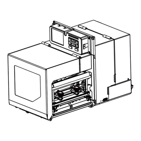
1. Fundamental of the System The PEX-2000 series are available in a left-hand configuration and a right-hand configuration. PEX-2XX0L series PEX-2XX0R series Left-hand model Right-hand model This document is going to show the components inside the media compartment of a left-hand print engine. A right-hand unit contains a mirror image of those components. -
Page 7: Printer Overview
1.1 Printer Overview Front View Wi-Fi antenna (option) LED indicator USB host Soft keys LCD display Power switch Media view window Media cover Print head pressure adjustment knob(s) (4 inch:1 pc/ 6 inch: 2 pcs) -
Page 8: Interior View
Interior View Ribbon rewind spindle Ribbon supply spindle Rear gap sensor LED adjustment bar (6 inch series only) Top black-mark sensor position adjustment bar Rear label holder lock Print head release lever Printhead Platen roller Peel-off roller release lever Media sensor position adjustment knob Rear label release button Front gap sensor Media sensor LED indicator... -
Page 9: Rear View
Rear View Power cord socket Rear cover handle Centronics interface GPIO interface (Applicator interface with DB15F connector +5V I/O) RS-232C interface Ethernet interface USB interface Micro SD card socket USB host Note: The interface picture here is for reference only. Please refer to the product specification for the interface availability. -
Page 10: Checking The Installation Space
1.2 Checking the Installation Space Please check the space for mounting the print engine into an applicator. Please refer to the dimensions in this section. 4 inch model Front view Front view with open media cover... - Page 11 Side view...
- Page 12 Top view Top view without media cover The distance between the ribbon and the printer frame. The distance between the media (includes liner, if any) and the printer frame.
-
Page 13: Inch Model
6 inch model Front view Front view with open media cover... - Page 14 Side view...
- Page 15 Top view Top view without media cover The distance between the ribbon and the printer frame. The distance between the media (includes liner, if any) and the printer frame.
-
Page 16: Electronics
2. Electronics 2.1 Summary of the Board Connectors Main Board 26 11 3 7 10... - Page 17 Connector Description USB host connector Power supply output (5V~24V DC) connector Wi-Fi Module connector Parallel Port board connector GPIO interface board connector Head open sensor connector Gap sensor connector Ribbon encoder sensor connector Power supply output (24V DC) connector BM sensor connector Paper distance sensor connector BT module connector Print head connector...
-
Page 18: Sensor Control Board
Sensor Control Board Connector Description Rear gap sensor connector/ transmit Front gap sensor connector/ transmit Front gap sensor connector/ receive Connector to main board (J2, J16, J24 and J25) Rear gap sensor connector/ receive & Lower BM sensor connector Upper BM sensor connector... -
Page 19: Interface Pin Configuration
2.2 Interface Pin Configuration RS-232C CONFIGURATION +5 V USB Device CONFIGURATION... - Page 20 Ethernet CONFIGURATION...
- Page 21 GPIO (Applicator interface with DB15F connector +5V I/O) CONFIGURATION 5V (JP2 short) GPI_1 GPI_2 GPI_3 GPI_4 GPO_1 GPO_2 GPO_3 GPO_4 GPO_5 GPO_6 GPO_7...
- Page 22 GPIO (Applicator interface with DB25F connector +5V I/O)/ Option CONFIGURATION FGND GPO_1 GPO_3 GPO_5 GPO_7 GPI_1 GPI_3 GPI_5 GPI_7 OUT_COM +24V OUT_COM GPO_2 GPO_4 GPO_6 GPO_8 GPI_2 GPI_4 GPI_6 GPI_8 IN_COM...
-
Page 23: Mechanism
3. Mechanism WARNING: Always unplug the printer power cord from the printer or power outlet before doing any replacement procedures. Failure to remove power could result in injury to you and damage to equipment. To prepare the printer for maintenance, follow the steps below. 1. -
Page 24: Replacing The Roller Assemblies
3.1 Replacing the Roller Assemblies Open printer media cover. For platen roller assembly, loosen one screw to release the platen roller lock as shown. Disengage print head release lever. - Page 25 Remove the platen roller assembly. Install the new platen roller assembly. For peel-off roller and rear pressing paper roller, loosen the screws to release the roller locks by the same way.
- Page 26 Open the peel-off cover by pressing the peel-off roller release lever to remove/replace the peel-off roller. Open the rear label holder cover by pushing the rear label release button to remove/replace the rear pressing paper roller. Reassemble the parts in the reverse procedures.
-
Page 27: Replacing The Printhead Assembly
3.2 Replacing the Printhead Assembly CAUTION: To prevent electrostatic damage to electronic components, ground yourself by touching an unpainted part of the printer frame before removing or installing the printhead assembly. Oils from your hands can damage the printhead. Do not touch the printhead when you handle the printhead assembly. Open printer media cover. - Page 28 Push the printhead assembly release latch to the right side to release the printhead assembly. Push the release tab down on the power supply cable assembly and remove the cable from the printhead assembly. Carefully remove the printhead controller cable assembly from the printhead assembly. Release tab Retainer clip...
- Page 29 Position the new printhead assembly below the pivoting deck and connect the printhead controller and power supply cable assemblies. Slide the printhead assembly upward into the pivoting deck until the retainer clip snap it in place. Make sure that the cable assemblies do not into the media or ribbon path.
-
Page 30: Replacing The Ribbon Spindle Assembly
3.3 Replacing the Ribbon Spindle Assembly Open printer media cover. Remove two screws on ribbon rewind spindle (or ribbon supply spindle) as shown. Please note that there is a washer between the printer frame and the spindle. Replace the new washer and ribbon spindle. Reassemble the parts in the reverse procedures. -
Page 31: Replacing The Media Cover Assembly
3.4 Replacing the Media Cover Assembly Open the media cover. Remove five screws on the cover as shown. Remove/ Replace the media cover assembly. Reassemble the parts in the reverse procedures. -
Page 32: Replacing The Power Supply Unit
3.5 Replacing the Power Supply Unit Remove two screws on both sides of the electronics cover as shown. Open the electronics cover. - Page 33 Disconnect three connectors on power supply unit as shown. Note: Because these connectors on the power supply are deeper, you can use the tool to loosen the tabs to disconnect them.
- Page 34 Remove four screws on the power supply unit as shown. Remove/Replace the power supply unit. Reassemble the parts in the reverse procedures.
-
Page 35: Replacing The Stepping Motor Assembly
3.6 Replacing the Stepping Motor Assembly Refer to section “Replacing the Roller Assemblies” to remove three roller assemblies. (Platen roller, peel-off roller and rear pressing paper roller) Loosen the cable tie, remove three screws, and disconnect one connector on the stepping motor assembly. Remove/Replace the stepping motor assembly. -
Page 36: Replacing The Belts
3.7 Replacing the Belts Refer to section “Replacing the Stepping Motor Assembly” to remove the stepping motor assembly. Remove five screws on stepping motor assembly to remove the belt cover. Note: Please note that when replacing the belt, DO NOT loosen or remove the screws on the motor assembly as shown in the figure below. - Page 37 Loosen two screws to the loosen the belt (W10 x L544) as shown, then tighten the two screws to secure this loose state. Remove/Replace the belt (W10 x L544).
- Page 38 Loosen two screw to the loosen the belt (W10 x L148) as shown, then tighten the two screws to secure this loose state.
- Page 39 Remove one screw to remove/replace the belt (W10 x L148). Reassemble the parts in the reverse procedures.
-
Page 40: Replacing The Ribbon Base Module Assembly
3.8 Replacing the Ribbon Base Module Assembly Refer to section “Replacing the Ribbon Spindle Assembly” to remove the ribbon support spindle and the ribbon rewind spindle. Refer to section “Replacing the Power Supply Unit” to open the electronics cover. Remove four screws (black) as shown and disconnect the cables to remove/replace the ribbon base module assembly. Reassemble the parts in the reverse procedures. -
Page 41: Replacing The Dc Motor Modules
3.9 Replacing the DC Motor Modules Refer to section “Replacing the Ribbon Base Module Assembly” to remove the ribbon base module assembly. Disconnect one connector and remove five screws to replace the DC motor assemblies. In back side, In back side, Reassemble the parts in the reverse procedures. -
Page 42: Replacing Gpio & Parallel Board And Usb Host Board
3.10 Replacing GPIO & Parallel Board and USB Host Board For Replacing GPIO DB15 Board: 1. Refer to section “Replacing the Power Supply Unit” to open the electronics cover, then open the main board cover. Or loosen the screws on both sides of the main board cover and remove whole main board cover as shown. - Page 43 2. Disconnect the two connectors and two screws as below to replace the USB host board. 3. Disconnect the two connectors (Note: Please unlock the plug from connect for the flat cable, and carefully pull the flat cable free.) and six screws as below to replace the GPIO board.
- Page 44 Note: This GPIO interface (Applicator interface with DB15F connector +5V I/O) supports internal 5V power supply (default). For external power supply, please remove the jumper on main board JP2. Internal power supply (5V I/O) External power supply (5~24V I/O) 4. Reassemble the parts in the reverse procedures. For Installing GPIO DB25 Board: 1.
- Page 45 2. Lock the below screws. 3. Put the lid and lock the below screws. 4. Reassemble the parts in the reverse procedures.
-
Page 46: Replacing The Main Board
3.11 Replacing the Main Board 1. Refer to section “Replacing the Power Supply Unit” & section “Replacing GPIO & Parallel Board and USB Host Board” to open the electronics cover and remove the GPIO board first. 2. Disconnect all connectors from the mainboard. Please unlock the plug from connect for the flat cable, and carefully pull the flat cable free. -
Page 47: Replacing The Sensor Control Board
3.12 Replacing the Sensor Control Board 1. Refer to section “Replacing the Power Supply Unit” to open the electronics cover. 2. Disconnect six connectors and remove two screws to replace the sensor control board. 3. Reassemble the parts in the reverse procedures. -
Page 48: Replacing The Panel Control Board & Lcd Panel
3.13 Replacing the Panel Control Board & LCD Panel Remove the marked fix LCD panel module four screws. Refer to section “Replacing the Power Supply Unit” to open the electronics cover. Loosen cable ties to remove the LCD panel assembly. - Page 49 Remover five screws and antenna (if installed/option) to remove the LCD rear cover. Remove the hex nut and washer as shown to open the LCD cover if installed. (option) Disconnect the connectors for power switch. Hex nut Washer...
- Page 50 Remove one screw to take out the Mylar. Disconnect three cable connectors. Please unlock the plug from connect for the flat cable, and carefully pull the flat cable free. And open the USB host cover.
- Page 51 Replace the panel control board and LCD panel. Reassemble the parts in the reverse procedures.
-
Page 52: Replacing The Peel-Off Roller Module
3.14 Replacing the Peel-off Roller Module Open the peel-off cover by pressing the peel-off roller release lever. Turn the thumb screw on the peel-off roller module to remove/replace the peel-off roller module. Reassemble the parts in the reverse procedures. -
Page 53: Replacing The Upper Print Module
3.15 Replacing the Upper Print Module Refer to section “Replacing the Power Supply Unit” to open the electronics cover. Refer to section “Replacing the Stepping Motor Assembly” & section “Replacing the Sensor Control Board” to remove the stepping motor assembly and the sensor control board. Disconnect the cables (two for printhead/ one for head open sensor) on main board. -
Page 54: Replacing The Sensor Holder Module
3.16 Replacing the Sensor Holder Module Refer to section “Replacing the Power Supply Unit” to open the electronics cover. Refer to section “Replacing the Stepping Motor Assembly” to remove the stepping motor assembly. Remove one screw as shown and disconnect two cables on sensor control board. Open the rear label holder cover by pushing the rear label release button. -
Page 55: Replacing/ Installing Wi-Fi Module (Option)
3.17 Replacing/ Installing Wi-Fi Module (Option) Refer to section “Replacing the Panel Control Board & LCD Panel” to remove LCD rear cover. For replacing, disconnect two cable connectors, two antenna cable connectors (use the U FL connector removal tool to carefully disconnect the antenna connector) and three screws to remove/ replace Wi-Fi module. - Page 56 Then, pull the Wi-Fi cables through the LCD rear cover and printer frame. Secure the LCD rear cover back by five screws. Install the LCD module by four screws. Secure the hex nuts and washers as shown for installing the antennas. Hex nut Wash Put the rubber ring on the bottom of the antenna to install the antennas.
- Page 57 Refer to section “Replacing GPIO & Parallel Board and USB Host Board” to remove the GPIO board. Connect the Wi-Fi cable connectors to main board, route the cables thread the wire saddle as shown. Reassemble the parts in reverse procedures.
-
Page 58: Replacing The Bluetooth Module (Option)
3.18 Replacing the Bluetooth Module (Option) Refer to section “Replacing the Panel Control Board & LCD Panel” to remove LCD rear cover. Disconnect one cable connector on main board (or connect on assembly) and three screws to replace bluetooth module. Bluetooth connector location on main board, Reassemble the parts in reverse procedures. -
Page 59: Replacing Rfid Module (Option)
3.19 Replacing RFID Module (Option) Remove two screws as shown to release the RFID module. Disconnect one cable to replace the RFID module. Reassemble the parts in the reverse procedures. -
Page 60: Installing Ribbon Saver Assembly (Option)
3.20 Installing Ribbon Saver Assembly (Option) Ribbon saver assembly (right-hand version) Ribbon saver cable Ribbon saver module Screw*2 (M4*L6 for fan) Screw*2 (M4xL10 for ribbon saver module) Note: This section is going to use a right-hand print engine to install the ribbon saver assembly. A left-hand unit contains a mirror image of those components. - Page 61 Connect the ribbon saver cable to the module board. Refer to section “Replacing the Power Supply Unit” to open the electronics cover, then open the main board cover.
- Page 62 Secure the fan to the printer frame using the two screws (M4*L6) provided in the kit. Note: Before installing the fan, please push the cable backwards. Secure the ribbon saver module to the printer frame using the two screws (M4xL10) provided in the kit. Note: When installing the ribbon saver, prevent to press the printhead cables or other cables.
- Page 63 Connect the fan cable to the module board and connect another side of ribbon saver cable to the main board. On ribbon saver module On main board Close the main board cover and secure the electronics cover. Make sure that the black non-woven fabric on the fan side must be removed.
-
Page 64: Troubleshooting
4. Troubleshooting 4.1 Common Problems Problem Possible Cause Recovery Procedure Power indicator does not * Plug the power cord in print engine and outlet. * The power cord is not properly connected. illuminate * Switch the power on. Carriage Open * The print head carriages are open. - Page 65 * SD card is damaged. * Use the supported capacity SD card. * SD card doesn’t insert correctly. * Insert the SD card again. SD card is unable to use * Use the non-approved SD card manufacturer. * Reload the supply. * Ribbon and media is loaded incorrectly * Clean the print head.
- Page 66 * Calibrate the sensor sensitivity again. * Set the correct label size and gap size. * Enter LCD menu (or via TSC Console) to fine tune the parameter of Shift Y. * If using the software BarTender, please set the vertical offset in the driver.
-
Page 67: Printing Adjustments
4.2 Printing Adjustments Moveable Printhead Pressure Adjustment The Moveable Print Head Pressure Adjustment has High/Low pressure adjustment. Because the printer’s paper alignment is located on the inboard side of the mechanism, different media widths require different pressure to print correctly. Therefore adjustment of pressure knob may be required to get your best print quality. There is one pressure knob for 4 inch series model and there are two pressure knobs for 6 inch series model. -
Page 68: Ribbon Tension Adjustment
Ribbon Tension Adjustment The Ribbon Tension Adjustment can adjust the ribbon tension level. Because the ribbon is aligned to the inward side of the printer mechanism, different ribbon or media widths may require different ribbon tension to print correctly. Therefore, it may be necessary to adjust the ribbon tension using the adjustment to avoid ribbon wrinkle and get the best print quality. -
Page 69: Ribbon Peeling Angle Adjustment
Ribbon Peeling Angle Adjustment The Ribbon Peeling Angle Adjustment can adjust the ribbon peeling angle with media. When the print quality is not good, the peeling angle can be changed to get the best print quality. Loosen two ribbon peeling angle screws to move the ribbon peeling plate up (Increasing angle) or down (Decreasing angle) for adjusting the ribbon peeling angle. -
Page 70: Printhead Burn Line Adjustment Screws
Printhead Burn Line Adjustment Screws The Printhead Burn Line Adjustment Screws are used to fine tune the print quality for different thicknesses of media. Turning the screws adjusts the print head’s burn line forward or backward as it relates to the platen roller. The print head burn line default is set for general purpose printing media (plain paper and paper thickness less than 0.20mm). -
Page 71: Tear Bar Angle Adjustment
Tear Bar Angle Adjustment The media tearing angle can be adjusted -18 ~ -3 degree by moving the Tear Bar. When you want to change the angle of the label exit in peel off mode or tear off mode, you can adjust the tear bar to get the best result. -
Page 72: Maintenance
5. Maintenance This session presents the clean tools and methods to maintain the printer. ◼ For Cleaning Depending on the media used, the printer may accumulate residues (media dust, adhesives, etc.) as a by-product of normal printing. To maintain the best printing quality, you should remove these residues by cleaning the printer periodically. Regularly clean the print head and supply sensors once change a new media to keep the printer at the optimized performance and extend printer life. - Page 73 Cleaning Tools ◼ Cotton swab ◼ Lint-free cloth ◼ Brush with soft non-metallic bristles ◼ Vacuum cleaner ◼ 75% Ethanol (for disinfecting) ◼ 99% Isopropyl alcohol (for printhead and platen roller cleaning) ◼ Genuine printhead cleaning pen ◼ Mild detergent (without chlorine) Cleaning Process: Printer Part Method...
-
Page 74: Revise History
Revise History Date Content Editor 2023/1/6 Release 6in (Rev.2) Camille 2023/4/15 Add 4in model info. Camille 2023/4/21 Add “Replacing the Bluetooth Module” section Camille 2023/4/24 Update “Replacing the Power Supply Unit” section Camille 2023/5/4 Add “Installing Ribbon Saver Assembly” section Camille 2023/5/17 Add a note on “Replacing the Belts”...
Need help?
Do you have a question about the PEX-2000 Series and is the answer not in the manual?
Questions and answers