
Subscribe to Our Youtube Channel
Related Manuals for TSC PEX-1120 Series


Summary of Contents for TSC PEX-1120 Series
- Page 1 PEX-1120/ PEX-1130/ PEX-1160 Series PEX-1220/ PEX-1230/ PEX-1260 Series THERMAL TRANSFER / DIRECT THERMAL PRINT ENGINE SERVICE MANUAL...
-
Page 2: Table Of Contents
PEX-1000 Series Print Engine Service Manua TABLE OF CONTENT 1. FUNDAMENTAL OF THE SYSTEM ................1 1.1. Print Engine Orientation ..................1 1.2. Overview ......................... 2 2. ELECTRONICS ......................5 2.1 Summary of Board Connectors ................5 2.2 Interface Pin Configuration ..................7 3. -
Page 3: Fundamental Of The System
PEX-1000 Series Print Engine Service Manua 1. FUNDAMENTAL OF THE SYSTEM 1.1. Print Engine Orientation The PEX-1000 series are available in a left-hand configuration and a right-hand configuration. PEX-1120/ PEX-1130/ PEX-1160 PEX-1220/ PEX-1230/ PEX-1260 series series Left-hand model Right -hand model Note: This document is going to show the components inside the media compartment of a left-hand print engine. -
Page 4: Overview
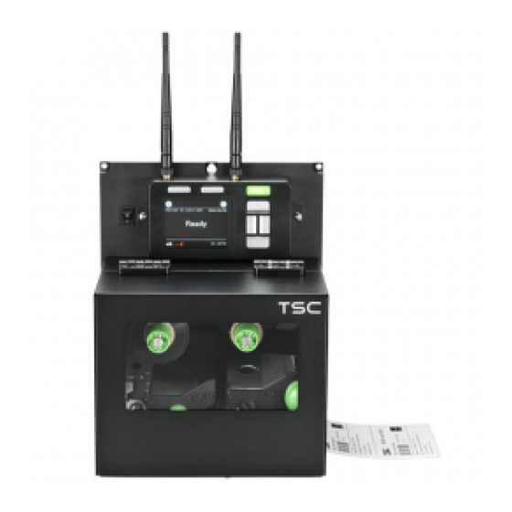
PEX-1000 Series Print Engine Service Manua 1.2. Overview Front View Soft keys Power switch LCD display Wi-Fi antenna (option) LED indicator Navigational keys Media view window Print engine cover USB host... - Page 5 PEX-1000 Series Print Engine Service Manua Interior View Ribbon rewind spindle Ribbon tension adjustment knobs Print head pressure adjustment knobs Print head release lever Print engine cover open sensor Ribbon supply spindle Label guide bar release lever Media sensor position adjustment knob Platen roller Print head Media sensor...
- Page 6 PEX-1000 Series Print Engine Service Manua Rear View GPIO interface (Applicator interface with DB15F connector +5V I/O) RS-232C interface Ethernet interface USB interface Note: Power cord socket The interface picture here is for reference only. Please refer to the Centronics interface product specification for the interfaces availability.
-
Page 7: Electronics
PEX-1000 Series Print Engine Service Manua 2. ELECTRONICS 2.1 Summary of Board Connectors... - Page 8 PEX-1000 Series Print Engine Service Manua Main board Connector Description USB Host connector Power supply output (5V~24V DC) connector Wi-Fi Module connector Parallel Port board connector GPIO interface board connector Head open sensor connector Gap sensor connector Ribbon encoder sensor connector Power supply output (24V DC) connector BM Sensor connector Paper Distance Sensor connector...
-
Page 9: Interface Pin Configuration
PEX-1000 Series Print Engine Service Manua 2.2 Interface Pin Configuration RS-232C CONFIGURATION +5 V CONFIGURATION Ethernet CONFIGURATION... - Page 10 PEX-1000 Series Print Engine Service Manua GPIO (Applicator interface with DB15F connector +5V I/O) CONFIGURATION 5V(JP2 short) GPI_1 GPI_2 GPI_3 GPI_4 GPO_1 GPO_2 GPO_3 GPO_4 GPO_5 GPO_6 GPO_7...
-
Page 11: Mechanism
PEX-1000 Series Print Engine Service Manua 3. MECHANISM 3.1 Replacing the Platen Roller Assembly 1. Open print engine cover. 2. Disengage print head release lever. 3. Remove three screws on the platen holder. Left-hand model Right -hand model 4. Take out the platen holder, tear bar and platen roller assembly and replace a new platen roller assembly. -
Page 12: Replacing The Print Head Assembly
PEX-1000 Series Print Engine Service Manua 3.2 Replacing the Print head Assembly 1. Loosen the print head secure screw counterclockwise until it can be taken out from the mechanism. 2. Disengage the print head release lever. Left-handed configuration Right -handed configuration 3. - Page 13 PEX-1000 Series Print Engine Service Manua 4. Remove/Replace the print head assembly. 5. Connect the print head cable and carefully slide print head assembly into the print mechanism. Make sure the two locating protrusion pins on the print mechanism mounting plate snap into the locating holes on the print head.
- Page 14 PEX-1000 Series Print Engine Service Manua 6. Check the print head has been totally closed to the print mechanism before secure the print head by the previously removed thumbscrew. 7. Reassemble the parts in the reverse procedures. Note: Please use the come with new print head secure screw to replace the print head assembly. DO NOT re-use the original screw.
-
Page 15: Remove The Electronics Cover
PEX-1000 Series Print Engine Service Manua 3.3 Remove the Electronics Cover 1. Remove four screws on the electronics cover. 2. Draw out the electronics cover to remove it. Electronics cover 3. Reassemble the parts in the reverse procedures. -
Page 16: Replacing The Power Supply Unit
PEX-1000 Series Print Engine Service Manua 3.4 Replacing the Power Supply Unit 1. Refer to section 3.3 to remove the electronics cover. 2. Disconnect three connectors as shown. 3. Remove two screws on power supply cover. - Page 17 PEX-1000 Series Print Engine Service Manua 4. Pull the power supply unit to loosen the cable tie and disconnect one connector as shown. 5. Remove/Replace the power supply unit. 6. Reassemble the parts in the reverse procedures.
-
Page 18: Replacing Multi-Interface (Gpio & Parallel) Board
PEX-1000 Series Print Engine Service Manua 3.5 Replacing Multi-interface (GPIO & parallel) Board 1. Refer to section 3.3 to remove the electronics cover. 2. Remove two screws on main board cover. 3. Disconnect the connectors as below shown first then disconnect all connectors on the main board to take out the main board unit. - Page 19 PEX-1000 Series Print Engine Service Manua 4. Disconnect two connectors and remove two screws on the multi-interface board. Note: This GPIO interface (Applicator interface with DB15F connector +5V I/O) supports internal 5V power supply (default). For external power supply, please remove the jumper on main board JP2. Internal power supply (5V I/O) External power supply (5~24V I/O)
- Page 20 PEX-1000 Series Print Engine Service Manua 5. Remove four screws on the cover as shown to loosen the GPIO and parallel ports. Note: Remove two screws to replace multi-interface plate if necessary. 6. Remove/Replace the multi-interface board. 7. Reassemble the parts in the reverse procedures.
-
Page 21: Replacing The Main Board
PEX-1000 Series Print Engine Service Manua 3.6 Replacing the Main Board 1. Refer to section 3.3 & 3.5 to remove the electronics cover and multi-interface board first. 2. Remove two copper pillars, four screws on the main board. Screws Copper pillars 3. -
Page 22: Replacing The Gap/Black Mark Sensor Module
PEX-1000 Series Print Engine Service Manua 3.7 Replacing the Gap/Black Mark Sensor Module Refer to section 3.6 to remove all connectors on the multi-interface board and main board. Pull the lower drawer (interface unit) and remove it. Lower drawer (interface unit) Pull the media sensor module and loosen the cable ties. - Page 23 PEX-1000 Series Print Engine Service Manua Remove/Replace the gap/black mark sensor. Gap/black mark sensor connectors Reassemble the parts in the reverse procedures.
-
Page 24: Replacing The Panel Control Board & Lcd Panel
PEX-1000 Series Print Engine Service Manua 3.8 Replacing the Panel Control Board & LCD Panel 1. Refer to section 3.3, 3.4 and 3.5 to remove the electronics cover, power supply unit and interface unit. 2. Remove the marked fix LCD panel module two screws. 3. - Page 25 PEX-1000 Series Print Engine Service Manua 4. Remover four screws and antenna antenna. 5. Remover the hex nut and washer as shown to open the LCD cover. Hex nut Washer 6. Remove two screws, three cables and open the USB host cover to replace the panel control board & LCD panel.
-
Page 26: Replacing The Bluetooth Module & Wi-Fi Module
PEX-1000 Series Print Engine Service Manua 3.9 Replacing the Bluetooth Module & Wi-Fi Module 1. Follow the previous section 3.8 to open the LCD cover. 2. For Bluetooth module, disconnect one cable connector and four screws to replace it. For Wi-Fi module, disconnect one cable connector, three screws and one antenna connector to replace it. -
Page 27: Replacing The Stepping Motor Assembly
PEX-1000 Series Print Engine Service Manua 3.10 Replacing the Stepping Motor Assembly Follow the previous step (refer to section 3.3, 3.4 and 3.5) to remove the electronics cover, power supply unit and interface unit. Remove four screws and one connector on the stepping motor assembly. Remove/Replace the stepping motor assembly (including belt, gears, stepping motor) Reassemble the parts in the reverse procedures. -
Page 28: Replacing The Peel-Off Roller Module
PEX-1000 Series Print Engine Service Manua 3.11 Replacing the Peel-off Roller Module 1. Open the peel-off roller release lever. Left-handed configuration Right -handed configuration 2. Turn the thumb screw on the peel-off roller module to remove/replace the peel-off roller module. Left-handed configuration Right -handed configuration... - Page 29 PEX-1000 Series Print Engine Service Manua 3. There is a locating hole between media sensor and rear paper-feed roller (most right one). Left-handed configuration Right -handed configuration 4. Put the shaft of the peel-off roller module into the locating hole. Left-handed configuration: Right -handed configuration:...
- Page 30 PEX-1000 Series Print Engine Service Manua 5. After putting shat into locating hole, at certain angle, the module would not be able to put inside. Please turn the module in the clockwise direct to put the module inside. Left-handed configuration: Right -handed configuration:...
- Page 31 PEX-1000 Series Print Engine Service Manua 6. Put back the golden color screw, and turn it in the clockwise direction to fix the screw. Left-handed configuration: Right -handed configuration: 7. Pushing the peel-off roller module upward. Left-handed configuration Right -handed configuration...
- Page 32 PEX-1000 Series Print Engine Service Manua 8. After hearing the click sound, the module is fixed to its position without dangling. Finished the installation of peel-off roller module. Left-handed configuration Right -handed configuration...
-
Page 33: Troubleshooting
PEX-1000 Series Print Engine Service Manua 4. TROUBLESHOOTING 4.1 Common Problems The following guide lists the most common problems that might be encountered when operating this bar code printer. If the printer still does not function after all suggested solutions have been invoked, please contact the Customer Service Department of your purchased reseller or distributor for assistance. - Page 34 PEX-1000 Series Print Engine Service Manua * Re-connect cable to interface. * If using serial cable, - Please replace the cable with pin to pin connected. - Check the baud rate setting. The default baud rate setting of printer is 9600,n,8,1. * If using the Ethernet cable, - Check if the Ethernet RJ-45 connector green LED is lit on..
- Page 35 PEX-1000 Series Print Engine Service Manua * Reload the supply. * Clean the print head. * Clean the platen roller. * Adjust the print density and print speed. * Run printer self-test and check the print head test pattern if there is dot missing in * Ribbon and media is loaded incorrectly the pattern.
- Page 36 PEX-1000 Series Print Engine Service Manua Multi interface board * Check if the board is plugged in the right * The installation is incorrect. connector. doesn’t work. Power and Error LEDs * Turn off the printer and wait all LEDs are * Power switch OFF and ON too fast.
-
Page 37: Mechanism Fine Adjustment To Avoid Ribbon Wrinkles
PEX-1000 Series Print Engine Service Manua 4.2 Mechanism Fine Adjustment to Avoid Ribbon Wrinkles This printer has been fully tested before delivery. There should be no ribbon wrinkle presented on the media for general-purpose printing application. Ribbon wrinkle is related to the media width, thickness, print head pressure balance, ribbon film characteristics, print darkness setting…etc. - Page 38 PEX-1000 Series Print Engine Service Manua The print head pressure adjustment knob has 5 levels of settings. “1” is the lowest pressure and “5” is the maximum pressure. Clockwise direction adjustment is to increase the print head pressure. Please only turn the pressure knobs in clockwise direction.
-
Page 39: Adjusting Heater Line
PEX-1000 Series Print Engine Service Manua 4.3 Adjusting Heater Line 1. Release 2 lock screws before you start to adjusting heater line screws. Heater line lock Heater line lock Heater line adjust Heater line adjust screw 2. Adjust heater line by right-side and left-side heater-line adjusting screws. - Page 40 PEX-1000 Series Print Engine Service Manua 3. In our standard testing procedure, we use Fasson semi-gloss paper and print a black bar as below picture. 4. Please do not use too high density for adjusting heater line. Because it would not be easy seeing the uneven printing if using too high density to print the black bar.
- Page 41 PEX-1000 Series Print Engine Service Manua GETSETTING$("SYSTEM","INFORMATION","SERIAL") PRINT 1 5. The lighter black bar may like left picture. 6. But sometime you can see one side has lighter density as below picture. 7. For this situation, please adjust right side heater line adjustment knob by clockwise direction until you see good density full average black.
- Page 42 PEX-1000 Series Print Engine Service Manua Sometimes when right side is ok, left size may become a little white. In this time you may need to adjust left side knob. 8. Until both side is full-average black , like the first one picture. Or like left side picture.
- Page 43 PEX-1000 Series Print Engine Service Manua 10. If this happens, please turn the heater line button in opposite direction. In the previous case, you may turn clockwise direction. Until you see the even picture I show you. 11. Then after adjusting it, lock the 2 locking screws to fix the heater line position. Note: For different thickness label, you may need to print out such pattern to see if this ...
-
Page 44: Maintenance
PEX-1000 Series Print Engine Service Manua 5. MAINTENANCE This session presents the clean tools and methods to maintain your printer. Please use one of following material to clean the printer. Cotton swab (Head cleaner pen) Lint-free cloth Vacuum / Blower brush ... - Page 45 PEX-1000 Series Print Engine Service Manua ethanol to wipe it. Compressed air blower or Monthly Sensor vacuum Wipe it with water-dampened As needed Exterior cloth Interior Brush or vacuum As needed Note: Do not touch printer head by bare hand. If you touch it careless, please use ethanol to ...
-
Page 46: Update History
PEX-1000 Series Print Engine Service Manua UPDATE HISTORY Date Content Editor - Modify GPIO information & update pictures 2019/1/4 Camille - Add GPIO interface Pin configuration 2019/9/4 Modify section 2.1 Camille... - Page 47 9F., No.95, Minquan Rd., Xindian Dist., No.35, Sec. 2, Ligong 1st Rd., Wujie Township, New Taipei City 23141, Taiwan (R.O.C.) Yilan County 26841, Taiwan (R.O.C.) TEL: +886-2-2218-6789 TEL: +886-3-990-6677 FAX: +886-2-2218-5678 FAX: +886-3-990-5577 Web site: www.tscprinters.com E-mail: apac_sales@tscprinters.com TSC Auto ID Technology Co., Ltd. tech_support@tscprinters.com...
Need help?
Do you have a question about the PEX-1120 Series and is the answer not in the manual?
Questions and answers