TSC PEX-2000 Series User Manual
Industrial barcode printers
Hide thumbs
Also See for PEX-2000 Series:
- Service manual (75 pages) ,
- User manual (130 pages) ,
- Programming manual (434 pages)

Related Manuals for TSC PEX-2000 Series


Summary of Contents for TSC PEX-2000 Series
- Page 1 PEX-2000 Series ◼ Direct Thermal ◼ Thermal Transfer Industrial Barcode Printers Series Lists: PEX-2260L User Manual PEX-2260R PEX-2360L PEX-2360R...
- Page 2 All other trademarks are the property of their respective owners. Information in this document is subject to change without notice and does not represent a commitment on the part of TSC Auto ID Technology Co. No part of this manual may be reproduced or transmitted in any form or by any means, for any purpose other than the purchaser’s personal use, without the...
-
Page 3: Table Of Contents
Table of Content Table of Content ......................................1 1. Introduction ........................................5 1.1 Product Specification ....................................6 2. Operation Overview ......................................9 2.1 Unpacking and Inspection ....................................9 2.2 Print Engine Orientation ..................................... 10 2.3 Checking the Installation Space ................................. 11 2.4 Printer Overview ......................................14 2.4.1 Front View ...................................... - Page 4 3.5.2 RFID Calibration ....................................32 4. TSC Console ........................................33 4.1 Start TSC Console ..................................... 33 4.2 Set Ethernet Interface ....................................35 4.3 Set Wi-Fi Interface ..................................... 37 4.4 Initialize the Printer Wi-Fi Setting ................................40 4.5 TPH Care ........................................41 4.6 Printer Function ......................................
- Page 5 5.4.6 GPIO-DB25 (Option/ Available on EZS Version firmware) ......................65 5.4.7 RFID (Option) ..................................... 69 5.5 Advanced ........................................75 5.6 File Manager ......................................77 5.7 Diagnostic ........................................78 5.8 Favorites ........................................79 6. GPIO Command Settings ....................................81 6.1 SET GPO ........................................81 6.2 SET GPI ........................................
- Page 6 8. Troubleshooting ......................................106 8.1 Common Problems ....................................106 8.2 Printing Adjustments ....................................109 Moveable Printhead Pressure Adjustment ............................. 109 Ribbon Tension Adjustment ..................................110 Ribbon Peeling Angle Adjustment ................................111 Tear Bar Angle Adjustment ..................................112 8.3 RFID Errors Message ....................................113 9.
-
Page 7: Introduction
Thank you very much for purchasing TSC bar code printer. TSC’s innovative PEX-2000 Series print engine incorporates a robust die cast construction designed for years of reliability, ease of use, and cost-conscious serviceability. The PEX combines a precision print mechanism with high performance electronics to produce labels at up to 14 inches per second, the fastest in its class. -
Page 8: Product Specification
1.1 Product Specification Printer 6-INCH: PEX-2260L/ PEX-2260R 6-INCH: PEX-2360L/ PEX-2360R Item Print resolution 8 dots/mm (203 DPI) 12 dots/mm (300 DPI) Printing method Thermal transfer and direct thermal Max. print speed (6-INCH) 356mm (14”)/ second 305mm (12”)/ second Max. print width 6-INCH: 168mm (6.61”) Max. - Page 9 ◼ 512MB Flash memory ◼ 512MB DDR2 RAM memory Memory ◼ USB device memory (FAT32) ◼ Micro SD card reader for memory expansion, up to 32GB ◼ RS-232 (Max. 115,200 bps ) ◼ USB 2.0 (High speed mode) Interface ◼ Internal Ethernet 10/100 Mbps ◼...
- Page 10 Media wound type Outside wound Media width (Label and 6-INCH: 50.8mm ~ 180mm (2“ ~ 7.09“) Liner) Standard (Default): 0.076 mm ~ 0.305 mm (2.99 mil ~ 12.01mil) Media thickness (Includes RFID Tag: liner, if any) 0.076 mm ~ 1.2 mm (2.99 mil ~ 47.2mil), lift up the front gap sensor wall when thickness >...
-
Page 11: Operation Overview
2. Operation Overview 2.1 Unpacking and Inspection This printer has been specially packaged to withstand damage during shipping. Please carefully inspect the packaging and printer upon receiving the bar code printer. Please retain the packaging materials in case you need to reship the printer. Unpacking the printer, the following items are included in the carton. -
Page 12: Print Engine Orientation
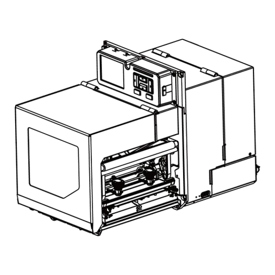
2.2 Print Engine Orientation The PEX-2000 series are available in a left-hand configuration and a right-hand configuration. PEX-2XX0L series PEX-2XX0R series Left-hand model Right-hand model Note: This document is going to show the components inside the media compartment of a left-hand print engine. A right-hand unit contains a mirror image of those components. -
Page 13: Checking The Installation Space
2.3 Checking the Installation Space Please check the space for mounting the print engine into an applicator. Please refer to the dimensions in this section. Front view Front view with open media cover... - Page 14 Side view...
- Page 15 Top view Top view without media cover The distance between the ribbon and the printer frame. The distance between the media (includes liner, if any) and the printer frame.
-
Page 16: Printer Overview
2.4 Printer Overview 2.4.1 Front View Wi-Fi antenna (option) LED indicator USB host Soft keys LCD display Power switch Media view window Printer cover Printhead pressure adjustment knob(s) -
Page 17: Interior View
2.4.2 Interior View Ribbon rewind spindle Ribbon supply spindle Rear gap sensor LED position adjustment bar Top black-mark sensor position adjustment bar Rear label holder lock Printhead release lever Printhead Platen roller Peel-off roller release lever Media sensor position adjustment knob Rear label release button Front gap sensor Media sensor LED indicator... -
Page 18: Rear View
2.4.3 Rear View Power cord socket Rear cover handle Centronics interface GPIO interface (Applicator interface with DB15F connector +5V I/O) RS-232C interface Ethernet interface USB interface Micro SD card socket USB host Note: The interface picture here is for reference only. Please refer to the product specification for the interfaces availability. -
Page 19: Operator Control
2.5 Operator Control Icons/ Time Printer mode & Firmware version Navigation Keys Printer Status Ethernet / Wi-Fi IP Soft Keys Icons 2.5.1 LED Indication and Keypads LED color indication: Color Meaning Solid: Power is on and ready to be used. (Green) Flash: System is downloading data or printer is paused. - Page 20 Keys Keypads form Item name Function The display will show the function for left and right key. The meaning of the soft Soft keys keys will depend on the UI screen. Navigational keys Select / Navigate Main Page Icons Icon Indication Wi-Fi device is ready (option).
- Page 21 Print engine cover open Enter the menu. Enter cursor (be marked in green) located option. Feed button (advance one label).
-
Page 22: Setup
3. Setup 3.1 Setting up the Printer Refer to the ch.2.3 to install the print engine to an applicator. Make sure the power switch is off. Connect the print engine to the computer with the provided USB cable or available connections. Plug the power cord into the AC power cord socket at the rear of the print engine, and then plug the power cord into a properly grounded power outlet. -
Page 23: Loading The Ribbon
3.2 Loading the Ribbon Open the media cover and the printhead mechanism. Right –hand model Left-hand model Install the ribbon and paper core onto ribbon supply spindle and ribbon rewind spindle. Right –hand model Left-hand model... - Page 24 Thread ribbon above the ribbon guide bar and through ribbon sensor slot. Right –hand model Left-hand model Wind the ribbon rewind spindle roughly 3~5 circles until ribbon is smooth, properly stretched and wrinkle-free. (ink coated outside available) Right –hand model Left-hand model...
-
Page 25: Loading The Media
3.3 Loading the Media Open the media cover and printhead mechanism. Open the label holder cover by pressing the rear label release button. Right –hand model Left-hand model Thread the leading edge of the label through the media guide bar pass media sensor, then place the leading edge onto the platen roller. - Page 26 Adjust the front label guide to fit the label width. Make sure the label through the front gap media sensor. Right –hand model Left-hand model Front gap media sensor Front gap media sensor Front label Front label guide guide Note: ⚫...
- Page 27 Move the rear media sensor by adjusting the media sensor position adjustment knob, make sure the sensor is able to sense the black-mark (back side) or gap on media. (Green = gap sensor/ Red = black-mark sensor) Right –hand model Left-hand model If the width of the gap is greater than 4 inches, you need to adjust the rear gap sensor LED position adjustment bar (as shown below) so that the sensor can align with the green LED.
- Page 28 If you use the media with black mark on the print side, you need to adjust the position of the black mark sensor. (as shown below) In the operation menu, select [Sensor] and then set the [Black Mark Location] to [Print Side]. After finishing the configuration, adjust the top black mark sensor so that the sensor can align with the black mark on the print side.
-
Page 29: Loading Media In Peel-Off Mode
3.4 Loading Media in Peel-off Mode Open the media cover and refer to ch.3.3 to load the media. Right –hand model Left-hand model Open printhead release lever and label guide bar release lever to thread the label through the front of the print engine and remove several labels. - Page 30 Open the peel-off roller release lever. Right –hand model Left-hand model Feed the leading edge of liner through the peel-off roller. Right –hand model Left-hand model...
- Page 31 Press the roller to close the peel-off roller release lever. Right –hand model Left-hand model Close printhead release lever and label guide bar release lever and press Feed button to test. Right –hand model Left-hand model...
-
Page 32: Setting Up The Rfid (Option)
3.5 Setting up the RFID (Option) 3.5.1 Reference Notes Smart labels are based on an EEPROM technology that requires some time to be programmed. You may notice this minor pause between labels. This time is necessary to better ensure consistent quality and improved reliability. When dealing with smart labels, it is possible that an occasional RFID tag may need to be written and verified more than once (retry) before being considered acceptable. - Page 33 TSC Auto ID disclaims any implied warranty of merchantability or fitness for a particular purpose. TSC Auto ID will not be liable under any circumstances for any damages or losses related in any way to use of these guidelines, specifications or other information, including damages which may be incurred as a result of labels not working properly in a specific application.
-
Page 34: Rfid Calibration
3.5.2 RFID Calibration The PEX-2000 printer has an RFID antenna coupler design that supports a wide variety of tag types. Right –hand model Left-hand model RFID Antenna RFID Antenna Refer to ch.3.3 to load the RFID media. Enter the operation menu list. Go to [Sensor] → [Auto Calibration] or [Preprint Calibration] to calibrate the media sensor first. Note: For RFID with gap type media, it is recommended to use this [Preprint Calibration] item for sensor calibration. -
Page 35: Tsc Console
4. TSC Console TSC Console is a management tool combining the Printer Management, Diagnostic Tool, CommTool and Printer Webpage settings, which enables you to adjust printer’s settings/status; change printers’ settings; download graphics, deploy fonts, graphics, label templates or upgrade the firmware to the group of printers, and send additional commands to printers at the same time 4.1 Start TSC Console... - Page 36 Select the current interface of the printer. The printer will be added to TSC Console’s interface. Select the printer and set the settings. For more information, please refer to TSC Console User Manual. ◼...
-
Page 37: Set Ethernet Interface
4.2 Set Ethernet Interface Use USB or COM to establish the interface on TSC Console. (If using the Wi-Fi interface before, Refer to section 5.5 to set the network interface to Ethernet.) Double click to enter the Printer Configuration Page > Click Ethernet tab > Check the IP Address. - Page 38 ◼ Choose Network > Key in the IP Address > Click Discover to establish the Ethernet interface. ◼ The notification will pop up > Click OK to close the window > The Ethernet interface will be shown on TSC Console.
-
Page 39: Set Wi-Fi Interface
4.3 Set Wi-Fi Interface Refer to ch.5.5 to set the network interface to Wi-Fi. Use USB or COM Port to set up the interface. (refer to chp.5.1) Double click to enter the printer configuration page. Click Get to receive printer’s information. Click Wi-Fi to the wi-fi setting page. - Page 40 For WPA-Personal Fill-in the SSID. Select the Encryption option to WPA-Personal. III. Fill-in the Key. Select DHCP to ON. (For OFF option, please fill-in the IP Address, Subnet Mask and Gateway) After setting, click the Set button. Note: Before setting, the entered field will be shown in yellow for reminding.
- Page 41 After clicking Set button, it'll pop-up the window tip as below shown. IP address will be shown in the “IP address” field and the Wi-Fi logo and IP address will be displayed on the LCD control panel. Note: IP address should be shown within about 5~15 seconds after printer turn on.
-
Page 42: Initialize The Printer Wi-Fi Setting
4.4 Initialize the Printer Wi-Fi Setting Return to the main page of TSC Console. Click Functions to expand the page. Click Wi-Fi Default to initialize the printer Wi-Fi module setting to factory default setting. -
Page 43: Tph Care
4.5 TPH Care TPH Care provides users to check the condition of the printhead and be able to set the dot failure threshold for indicating errors when the threshold is triggered. This option is used to set the treshhold for unhealthy TPH dot This option is used to enable (ON)/ disable (OFF) the TPH number. -
Page 44: Printer Function
4.6 Printer Function Printer Function could be found in Printer Configuration. “Printer Function” will be shown on the left side of the window. Functions Description Calibrate Sensor Detect media types and the size of the label RTC Setup Synchronize printer with Real Time Clock on PC Factory Default Initialize the printer to default settings Reset Printer... -
Page 45: Setting Post-Print Action
Follow below procedure to set the post action for the printing: Refer ch.5.1 to Connect the printer with TSC Console > Double click the printer > The Printer Configuration Page will pop up > Click Get to load information > Go to Common Tab > Find Post-Print Action > Select the mode depends on users’ application > Click Set. -
Page 46: Setting Rfid
4.8 Setting RFID Press [RFID] button from Printer Function to enter the RFID menu on TSC Console. Here provides users to set the RFID common settings, RFID calibration and checking statistics. Item Description OFF/ ON Select ON/OFF to enable/disable the RFID encoder module. - Page 47 OFF/ ON This menu item determines if errors are declared when the Label Retry count is exceeded. This RFID button is used to do RFID calibration, and get the three parameters through RFID calibration. Note: Before performing an RFID calibration, you will first need to select the right sensor for your RFID labels and run a media sensor calibration.
-
Page 48: Lcd Menu Function
5. LCD Menu Function 5.1 Menu Overview There are 6 categories on the menu. Users can easily set the settings of the printer without connecting the computer. Please refer to following sections for more details. Advanced: To set LCD, initialization, cutter Setting: To set up the printer settings for TSPL &... -
Page 49: Setting
Press the right soft key to switch the TSPL, ZPL2, and SBPL. Select the item by navigational key and press right soft key to enter the selected item. Note: TSPL is TSC ® printer language. ZPL2 is an emulation of Zebra ®... -
Page 50: Tspl
5.2.1 TSPL TSPL category can set up the printer settings for TSPL. Speed Slew Speed Back Speed Density Direction Batch Mode Print mode Applicator TSPL Offset Rewinder Mode Shift X Shift Y Reference X Reference Y Code Page Country... - Page 51 Item Description Default 203 dpi: 6 Speed Set the print speed. 300 dpi: 4 203 dpi: 6 Slew Speed Set feed speed 300 dpi: 4 Back Speed Set back speed Density Set printing darkness. Setting range: 0 to 15, and the step is 1. Set the printout direction.
-
Page 52: Zpl2
5.2.2 ZPL2 This “ZPL2” category can set up the printer settings for ZPL2. Darkness Print Speed Slew Speed BackFeed Speed Tear Off Tear Off Applicator Print Mode Stream Print Width Rewind List Fonts List Images List Formats List Setup Setting ZPL2 Control Prefix Format Prefix... - Page 53 Item Description Default Density Set the printing darkness. Available setting range: 0 to 30. 203 dpi: 6 Print Speed Set the print speed. 300 dpi: 4 203 dpi: 6 Slew Speed Set feed speed 300 dpi: 4 BackFeed Speed Set back speed Tear Off Adjust media stop location.
- Page 54 Set the action of the media when turning on the printer. Feed: Printer will advance one label. Media Power Up Calibration: Printer will make calibration. No Motion Length: Printer determine length and feed label. No Motion: Printer will not move media. Set the action of the media when closing the printhead.
-
Page 55: Sbpl (Only Available On Ezs Version Firmware)
5.2.3 SBPL Only available on EZS version firmware) Print Type Dispenser Print Darkness Rewinder Mode Print Speed(S) Continuous Setting SBPL Slew Speed(S) BackFeed Speed(S) Offset Pitch Item Description Default This item is used to set the print mode. There are three modes as below, Dispenser Once printer complete printing 1 label, it will wait for being removed. -
Page 56: Sensor
5.3 Sensor This option is used to calibrate the selected sensor. We recommend calibrate the sensor before printing when changing the media. Auto Calibration Black Mark Continuous Preprint Calibration Black Mark Manual Calibration Black Mark Continuous Menu Sensor Auto Threshold Detect Fixed Gap Location Blackmark Location... -
Page 57: Interface
This option is used to set the upper or lower black mark sensor as the primary transmitter. Please Black Mark Location Back side set it according to the position of the black marker on the media (Back side/ Print side) Cover Error Enable pop up the error when opening the media cover Disable... -
Page 58: Serial Comm
5.4.1 Serial Comm Serial comm can set the printer RS-232 settings. 1200 bps 2400 bps 4800 bps 9600 bps Baud Rate 19200 bps 38400 bps 57600 bps 115200 bps None Menu Interface Serial Parity Even Data Bits Stop Bit(s) Item Description Default Baud Rate... -
Page 59: Ethernet
5.4.2 Ethernet Ethernet configures internal Ethernet configuration and checks the printer’s Ethernet module status, and reset the Ethernet module. Ethernet Network Interface Wi-Fi Menu Interface Ethernet Status Configure Item Description Default Network Interface Select the network interface by Wi-Fi or Ethernet. Status Check the Ethernet IP address and MAC setting status. -
Page 60: Wi-Fi
5.4.3 Wi-Fi Wi-Fi can set the printer Wi-Fi settings. Ethernet Network Interface Wi-Fi Status Config Menu Interface Wi-Fi SSID Security Password Item Description Default Network Interface Select the network interface by Wi-Fi or Ethernet. Status Check the Wi-Fi IP address, MAC setting status,…etc. DHCP: ON/OFF the DHCP (Dynamic Host Configuration Protocol) network protocol. -
Page 61: Bluetooth
5.4.4 Bluetooth Bluetooth can set the printer Bluetooth settings. Status Local Name Menu Interface Bluetooth Ping Code Item Description Default Status Check the Bluetooth status. Local Name Set the local name for Bluetooth. RF-BHS Ping Code Set the local ping code for Bluetooth. 5.4.5 GPIO This option is used to set the print engine GPIO settings. - Page 62 Item Description Default This option is used to set the GPO_3 signal when PRINT END. Selections Description The applicator port is off. Label Label Waiting Label prints Ready format format for start for next sent processed print label signal Not ready Data ready Applicator Port...
- Page 63 Label Label Waiting Label prints Ready format format for start for next sent processed print label signal Data Not ready ready (Pin 14, Ready GPO_6) Do not Print start start Start (Pin 3, GPI_1) Print Do not Mode 2 (Pin 11, GPO_3)
- Page 64 Label Label Waiting Label prints Ready for format format for start next label sent processed print signal Data ready ready (Pin 14, Ready Mode 3 GPO_6) Print Do not start start (Pin 3, Start GPI_1) Print Do not (Pin 11, GPO_3)
- Page 65 Label Label Waiting Lab el prints Ready for format format for start next label sent processed print signal Data ready ready (Pin 14, Ready Mode 4 GPO_6) Print Do not start start (Pin 3, Start GPI_1) Print Do not (Pin 11, GPO_3) Use GPIO setting commands for customized settings.
- Page 66 Start Print SIG This determines the trigger conditions for the printer to control GPI 1 and GPI4. Level mode Error On Enable When this option is enabled and the printer is paused, the error signal (GPO_2) is LOW. Pause Ribbon Low When this option is enabled and the printer is Low Ribbon (GPO_1), the printer will generate a warning.
-
Page 67: Gpio-Db25 (Option/ Available On Ezs Version Firmware)
5.4.6 GPIO-DB25 (Option/ Available on EZS Version firmware) Before BackFeed Motion Controlled After Mode 1 Ext 9 Pin Select Mode 2 Type 1 Type 2 External Signal Type 3 Type 4 Menu GPIO Interface Enable External Reprint Disable Enable Continuous Print Disable I/O Status I/O Signal... - Page 68 Item Description Default Set the Backfeed motion in dispenser mode BEFORE: Backfeed the media to the printhead position before printing Before BackFeed Motion AFTER: Backfeed the label after dispensing CONTROLED: Backfeed motion will be controlled by external signal Set the output mode of the external signal pin 6 when using a 25-pin connector Ext 9 Pin Select Mode 1 MODE1: Outputs the signal when the product has/does not have remaining print data.
- Page 69 First label complete Type 1,2 Print Start Print Print End Type 3,4 First label complete Print Start Print...
- Page 70 Print End Use external signal to trigger the reprint signal to access reprint function External Reprint Disable ENABLE: Enable the reprint DISABLE: Disable the reprint Use external signal to trigger the Print start signal to access reprint function Continuous Print Disable ENABLE: Enable the continuous print DISABLE: Disable the continuous print...
-
Page 71: Rfid (Option)
5.4.7 RFID (Option) Label Retry Max Retry Error EPC Write Ctrl Error Handing Non-RFID Warning RFID Active Control Do RFID Calibrate Num Label for Calibration Test EPC Length Tag Calibration Tag Position Write Power Read Power Calibration Param USR Size Interface RFID TID Size... - Page 72 Item Description Default Wi-Fi Status Check the Wi-Fi status Configure Set the Wi-Fi configure DHCP SSID Set the SSID Security Set the security Open Password Set the security key Bluetooth Status Check the Bluetooth status Local Name Set the local name for Bluetooth RFID Control RFID Active:...
- Page 73 RFID This submenu is used to do RFID calibration. The user must do the tag calibration when installing a new tag in the printer. RFID calibration operation determines the RFID chip type, the write/read power, program position, length Calibration of the EPC/User field. Do RFID The executable item performs RFID calibration.
- Page 74 RFID RFID Chip It is used to configure the system when support of custom RFID tags is required. Param USR Size This menu item selects the size in bytes of the USR block within the RFID tag memory. Normally, this value is set automatically by the RFID calibration process and should not be changed.
- Page 75 Block Size This menu item selects the maximum number of bytes written to the USR block within the RFID tag memory at one time. Normally, this value is set automatically by the RFID calibration process and should not be changed. Minimum Maximum Default...
- Page 76 This menu item does not position the RFID tag over the coupler. Make sure to position the tag over the coupler to receive an accurate writing. Write EPC This executable menu writes all twos to the tag in range of the internal RFID coupler. It is with 2s primarily intended for development verification by checking that the system is working.
-
Page 77: Advanced
5.5 Advanced Language Printer Information Initialization Date Format Display Brightness Date Date & Time Time Format Time Menu Lock Security Menu Password Menu Advanced Ribbon Wound Ribbon Tension Ribbon Low Warning Warning Printer Head Maintn Reset Counter Interval Key Sound Pause Mode LCD Invert Contact Us... - Page 78 Date & Time Setup the date and time on display. Security Set the password for locking the menu or favorites. The default password is 8888. Disable Ribbon Wound Set the ribbon wound direction. Ink Side Out Ribbon Tension Set the ribbon tension. Medium Set the warning for ribbon low.
-
Page 79: File Manager
5.6 File Manager File Manager is used to check the printer available memory, show the files list, delete the files or run the files that saved in the printer DRAM/Flash/Card memory. DRAM Menu File Manager FLASH CARD Item Description DRAM Use this menu to show, delete and run (.BAS) the files saved in the printer DRAM memory. -
Page 80: Diagnostic
5.7 Diagnostic Print Config. Dump Mode Menu Diagnostic Printhead Diag Gap Display Diag Black Mark Sensor Diag Ribbon End Diag Media Item Description Print current printer configuration to the label. The configuration printout contains printhead test pattern, which is useful Print Config. -
Page 81: Favorites
5.8 Favorites This feature can create customized menu list. You can organize the commonly used setting options to the Favorites list. Enter Favorites List Press and hold the left side soft key on Ready mode to enter Favorites. (Default: No items in the list) Press and hold left soft keys... - Page 82 Add List to Favorite Select one option item, and press and hold the right soft key until Join Favorites window pops up. Select “Yes” to add the item to Favorites list. Press and hold the right soft key Delete Items From Favorite Select one option item, and press and hold the right soft key until Delete Favorites window pops up.
-
Page 83: Gpio Command Settings
6. GPIO Command Settings 6.1 SET GPO Description Use this command to send out the GPIO signals by the printer. Syntax SET GPOn signal state, delay0, pulse0, delay1, pulse1, function condition Parameter Description n = 1 ~ 7 Seven dedicated outputs are available for the desired function conditions. HIGH Goes the high level signal when the following function condition is detected. - Page 84 After detecting the following function condition, the printer will wait this period of time before sending out the “false” output signal. Delay1 Unit: millisecond. Maximum: 32000. Pulse width corresponding to the function condition becoming “false”. (Ignored for level-type signals.) Pulse1 Unit: millisecond.
-
Page 85: Set Gpi
6.2 SET GPI Description Use this command to receive the GPIO signals from external controlling devices. Syntax SET GPIn signal, pulse, function Parameter Description n = 1 ~ 4 Four dedicated inputs are available for the desired control functions. HIGH When a high level signal received, will activate the following printer control functions. - Page 86 Sample Code Example SET GPI1 HIGH,0,PAUSE SET GPI2 LOW,0,PAUSE ON SET GPI3 POS,100,PAUSE OFF SET GPI4 NEG,100,CUT SET GPI1 NEG,100,INPUT “TEST.BAS”+CHR$(13)+CHR$(10)
- Page 87 GPIO Waveform GPI Level Signal : Continuous action. (Host to printer.) GPI Pulse Signal : A pulse is an action. (Host to printer.)
- Page 88 GPO Level Signal : Continuous condition. (Printer to host.) GPO Pulse Signal : A pulse is a condition. (Printer to host.)
- Page 89 GPO pin no. 1~7 application example: Since we connect GPO pin no. 1~7 with seven individual LED, the output signal from GPO will light the individual LED on or off. *NPN output specification. Collector-emitter voltage 35 V Emitter-collector voltage Collector current Max.
-
Page 90: Applicator I/O Interface (Db15F) Circuit Diagram
Applicator I/O Interface (DB15F) Circuit Diagram PEX-1000 series... -
Page 91: Applicator I/O Interface (Db25F/ Option) Circuit Diagram
Applicator I/O Interface (DB25F/ Option) Circuit Diagram... - Page 93 Below table’s emulation will only be applied when users are using GPIO-DB25 with the External Signal function turned on(Type 1/2/3/4). Please follow the procedures to trun on the function: Menu > Interface > GPIO > External Signal (Defualt:Off) > Type1/2/3/4. CONFIGURATION SIGNAL NAME SIGNAL TYPE...
- Page 94 GPO_6 Low Ribbon Output High GPO_8 Reverse Output GPI_2 Start Print Input GPI_4 Formfeed Input GPI_6 Reverse Input GPI_8 Reverse Input IN_COM IN_COM Input GND(SIGNAL GROND)
-
Page 95: Rfid Setting Commands
7. RFID Setting Commands Incorporate RFID commands into new or existing printer programs. IMPORTANT: With all examples make sure the label length matches the physical length of the installed media. 7.1 RFID ON/OFF Description This command is used to enable/disable the RFID encoder module. Syntax RFID ON/OFF Parameter... -
Page 96: Rfid Error
7.2 RFID ERROR Description If an error persists after the specified number of labels are tried, perform this error handling action. Syntax RFID ERROR OFF/STOP/OVERSTRIKE Parameter Description No specific action is taken when a tag fails to be programmed. STOP Place printer in Pause mode. -
Page 97: Rfid Retry
7.3 RFID RETRY Description This command is used to set the number of label retries that the RFID encoder will attempt before declaring a fault. Syntax RFID RETRY # Parameter Description Number of retries (1 ~ 10) Sample Code Example RFID RETRY 2... -
Page 98: Rfid Retryerror On/Off
7.4 RFID RETRYERROR ON/OFF Description This command is used to set if errors are declared when the Label Retry count is exceeded. Syntax RFID RETRYERROR ON/OFF Parameter Description Enable the RFID retry error function Disable the RFID retry error function Sample Code Example RFID RETRYERROR OFF... -
Page 99: Rfid Position
7.5 RFID POSITION Description This command is used to set the how far the RFID tag encoding position of the currently installed tag should be offset from Top of Form. Normally, this value is set automatically by the RFID calibration process and should not be changed. Syntax RFID POSITION # Parameter... -
Page 100: Rfid Power
7.6 RFID POWER Description This command is used to set the for optimal tag encoding. Sets the read/write power level to be used in the RFID encoder. Normally, this value is set automatically by the RFID calibration process and should not be changed. Syntax RFID POWER read,write Parameter... -
Page 101: Rfid Countreset
7.7 RFID COUNTRESET Description This command is used to clear the total/failed tag statistics counters. Syntax RFID COUNTERSET Parameter Description Sample Code Example RFID COUNTERSET... -
Page 102: Rfid Read/Write
7.8 RFID READ/WRITE Description This command allows you to write or read to an RFID tag. Syntax RFID a,b,format,start block,size,memory bank,data Parameter Description WRITE = write to the tag READ = read the tag WRITE lock 0 = write without lock. only password 1 to FFFFFFFF in hex = write and lock... - Page 103 memory bank EPC - EPC 12 bytes data area - Tag identification 8 bytes area (currently not applicable for RFID WRITE) USR - User 32 bytes area ACS - 4 bytes access code area - 4 bytes kill code area - 2 bytes PC code area (Gen 2 tags only) data WRITE = content of data string...
- Page 104 Example 2 This programming example writes a data with lock password into an RFID tag and reads the written data with a prompt. RFID WRITE,1234,H,0,8,EPC,"20191008" RFID READ,0,H,0,8,EPC,"Date: " PRINT 1 For this locked RFID tag, it cannot be overwritten data without using RFID READ unlock password command. If you re-send the RFID WRITE command, the printer LCD will be shown as below,...
- Page 105 If you need to overwrite this locked tag, please use RFID READ unlock command as following programming example, to unlock password for the RFID tag so it can be overwritten later. RFID READ,1234,H,0,8,EPC,"Date: " PRINT 1 RFID WRITE,0,H,0,12,EPC,"123456789012" RFID READ,0,H,0,12,EPC,"Read Data: " PRINT 1 Example 3 When using WRITE, if the "size"...
- Page 106 RFID WRITE,0,H,0,8,EPC,"1234" RFID READ,0,H,0,12,EPC,"Read Data: " PRINT 1 Example 4 (EPC & USR with Lock) RFID WRITE,12345678,H,0,12,EPC,"123456789012" RFID WRITE,12345678,H,0,12,USR,"987654321012" RFID READ,12345678,H,0,12,EPC,"EPC : " RFID READ,12345678,H,0,12,USR,"USR : " PRINT 1 Example 5 (EPC & USR & ACS with Lock) RFID WRITE,12345678,H,0,12,EPC,"123456789012" RFID WRITE,12345678,H,0,12,USR,"987654321012"...
- Page 107 RFID READ,12345678,H,0,12,USR,"USR : " PRINT 1 Example 6 (EPC & USR & ACS & KIL with Lock) RFID WRITE,12345678,H,0,12,EPC,"123456789012" RFID WRITE,12345678,H,0,12,USR,"987654321012" RFID WRITE,12345678,H,0,8,ACS,"12345678" RFID WRITE,12345678,H,0,8,KIL,"12345678" RFID READ,12345678,H,0,8,ACS,"ACS : " RFID READ,12345678,H,0,8,KIL,"KIL : " RFID READ,12345678,H,0,12,EPC,"EPC : " RFID READ,12345678,H,0,12,USR,"USR : " PRINT 1 Example 7 (PC+EPC) RFID WRITE,0,H,0,4,PC,"3400"...
-
Page 108: Troubleshooting
8. Troubleshooting 8.1 Common Problems Problem Possible Cause Recovery Procedure Power indicator does not * Plug the power cord in print engine and outlet. * The power cord is not properly connected. illuminate * Switch the power on. Carriage Open * The printhead carriages are open. - Page 109 * SD card is damaged. * Use the supported capacity SD card. * SD card doesn’t insert correctly. * Insert the SD card again. SD card is unable to use * Use the non-approved SD card manufacturer. * Reload the supply. * Ribbon and media is loaded incorrectly * Clean the printhead.
- Page 110 * Calibrate the sensor sensitivity again. * Set the correct label size and gap size. * Enter LCD menu (or via TSC Console) to fine tune the parameter of Shift Y. * If using the software BarTender, please set the vertical offset in the driver.
-
Page 111: Printing Adjustments
8.2 Printing Adjustments Moveable Printhead Pressure Adjustment The Moveable Printhead Pressure Adjustment has High/Low pressure adjustment. Because the printer’s paper alignment is located on the inboard side of the mechanism, different media widths require different pressure to print correctly. Therefore adjustment of pressure knob may be required to get your best print quality. Turn the knob to L (Decreasing pressure) or H (Increasing pressure) to adjust the printhead pressure. -
Page 112: Ribbon Tension Adjustment
Ribbon Tension Adjustment The Ribbon Tension Adjustment can adjust the ribbon tension level. Because the ribbon is aligned to the inward side of the printer mechanism, different ribbon or media widths may require different ribbon tension to print correctly. Therefore, it may be necessary to adjust the ribbon tension using the adjustment to avoid ribbon wrinkle and get the best print quality. -
Page 113: Ribbon Peeling Angle Adjustment
Ribbon Peeling Angle Adjustment The Ribbon Peeling Angle Adjustment can adjust the ribbon peeling angle with media. When the print quality is not good, the peeling angle can be changed to get the best print quality. Loosen two ribbon peeling angle screws to move the ribbon peeling plate up (Increasing angle) or down (Decreasing angle) for adjusting the ribbon peeling angle. -
Page 114: Tear Bar Angle Adjustment
Tear Bar Angle Adjustment The media tearing angle can be adjusted -18 ~ -3 degree by moving the Tear Bar. When you want to change the angle of the label exit in peel off mode or tear off mode, you can adjust the tear bar to get the best result. -
Page 115: Rfid Errors Message
8.3 RFID Errors Message The RFID encoder can detect a number of errors. When one of these errors occurs, the RFID encoder alerts the printer to perform the currently selected error action and display the appropriate error message on the control panel’s LCD. Error Message Possible Cause Recovery Procedure... - Page 116 The RFID command is sent to the printer, Please go to RFID > Control > RFID Active to enable the RFID. ◼ ◼ but RFID is disabled. ◼ Then process RFID commands. ◼ When the "Non- RFID warning" option is "ON"...
- Page 117 ◼ The label could be misaligned. Perform the Sensor > Auto Calibration procedure to ensure the label is at top-of-form. ◼ Perform the FRID > Control > Tag Calibration > RFID Calibrate. ◼ Make sure the media are smart labels with RFID tags located ◼...
-
Page 118: Maintenance
9. Maintenance This session presents the clean tools and methods to maintain the printer. ◼ For Cleaning Depending on the media used, the printer may accumulate residues (media dust, adhesives, etc.) as a by-product of normal printing. To maintain the best printing quality, you should remove these residues by cleaning the printer periodically. Regularly clean the printhead and supply sensors once change a new media to keep the printer at the optimized performance and extend printer life. - Page 119 Cleaning Tools ◼ Cotton swab ◼ Lint-free cloth ◼ Brush with soft non-metallic bristles ◼ Vacuum cleaner ◼ 75% Ethanol (for disinfecting) ◼ 99% Isopropyl alcohol (for printhead and platen roller cleaning) ◼ Genuine printhead cleaning pen ◼ Mild detergent (without chlorine) Cleaning Process: Printer Part Method...
-
Page 120: Agency Compliance And Approvals
10. Agency Compliance and Approvals EN 55032: Class A EN 55024 EN 55035 EN 61000 EN 60950-1 EN 62368-1 This is a class A product. In a domestic environment this product may cause radio interference in which case the user may be required to take adequate measures. FCC part 15B, Class A ICES-003, Class A This equipment has been tested and found to comply with the limits for a Class A digital device, pursuant to... - Page 121 UL 62368-1 CAN/CSA-C22.2 NO. 62368-1 KS C 9832 KS C 9835 KC62368-1 이 기기는 업무용(A 급) 전자파적합기기로서 판매자 또는 사용자는 이 점을 주의하시기 바라며, 가정외의 지역에서 사용하는 것을 목적으로 합니다. GB 4943.1 GB/T9254, Class A GB 17625.1 警告:在居住环境中,运行此设备可能会造成无线电干扰。 Energy Star for Imaging Equipment Version 3.0 TP TC 004 TP TC 020 CNS15598-1...
- Page 122 4. The mains socket shall be installed near the equipment and easily accessible. 5. The unit must be protected against moisture. 6. Ensure the stability when installing the device, Tipping or dropping could cause damage. 7. Make sure to follow the correct power rating and power type indicated on marking label provided by manufacture. 8.
- Page 123 CAUTION: For equipment with RTC (CR2032) battery or rechargeable battery pack Risk of explosion if battery is replaced by an incorrect type. Dispose of used batteries according to the Instructions as below. 1. DO NOT throw the battery in fire. 2.
- Page 124 IMPORTANT : Retirer l’alimentation de l’entrée CA avant d’ouvrir le capot des consommables pour procéder au nettoyage ou à la réparation de l'appareil.. Après avoir effectué le nettoyage ou corrigé les dysfonctionnements, fermez le capot des consommables avant de brancher l’alimentation à l’entrée CA. CAUTION: Any changes or modifications not expressly approved by the grantee of this device could void the user's authority to operate the equipment.
- Page 125 30mW 5470-5725MHz Hereby, TSC Auto ID Technology Co., Ltd. declares that the radio equipment type [Wi-Fi] IEEE 802.11 a/b/g/n is in compliance with Directive 2014/53/EU The full text of the EU declaration of conformity is available at the following internet address: http:// www.tscprinters.com...
- Page 126 specific host products operated in portable exposure conditions. (For Wi-Fi) This device has also been evaluated and shown compliant with the IC RF Exposure limits under portable exposure conditions. (Antennas are less than 20 cm of a person's body). (For Bluetooth) Canada, avis de l'Industry Canada (IC) Cet appareil numérique de classe B est conforme aux normes canadiennes ICES-003 et RSS-210.
- Page 127 限用物質含有情況標示聲明書/ Declaration of the Presence Condition of the Restricted Substances Marking 設備名稱:熱轉式/熱感式條碼印表機 / Barcode Printer 主型號: 系列型號 PEX-2000-6 Equipment name Type designation (Type) 限用物質及其化學符號 Restricted substances and its chemical symbols 六價鉻 多溴聯苯 多溴二苯醚 鉛 汞 鎘 Lead Mercury Cadmium Hexavalent Polybrominated Polybrominated 單元...
- Page 128 備考1.〝超出0.1 wt %〞及〝超出0.01 wt %〞係指限用物質之百分比含量超出百分比含量基準值。 Note 1:“Exceeding 0.1 wt %” and “exceeding 0.01 wt %” indicate that the percentage content of the restricted substance exceeds the reference percentage value of presence condition. 備考2.〝○〞係指該項限用物質之百分比含量未超出百分比含量基準值。 Note 2:“○” indicates that the percentage content of the restricted substance does not exceed the percentage of reference value of presence. 備考3.〝-〞係指該項限用物質為排除項目。...
-
Page 129: Revision History
Revision History Date Content Editor 2023/1/6 Release 6in/ Rev.3 Camille...
Need help?
Do you have a question about the PEX-2000 Series and is the answer not in the manual?
Questions and answers