Advertisement
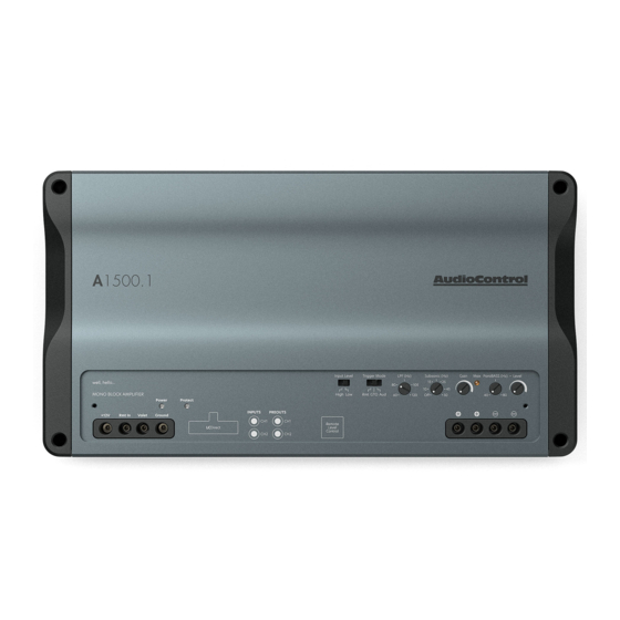
A1500.1
A1500.1 TOP SS ARTWORK - 2 PASS LASER ETCH
PASS1 : LASER ETCH/COLOR REMOVAL - RAW ALUMINUM
A1500.1
A1200.1 FRONT SS ARTWORK - 1 PASS
PASS 1: DARK LASER MARKING/ANNEALING - DARK GRAY
Features
• 1 x 600 W @ 4 Ohms, 1 x 1200 W @ 2 Ohms, 1 x 1500 W @ 1.33 Ohms
• High Current Design
• 2 RCA Line Inputs
• 2 RCA Line Outputs
• GTO
Signal Sense
TM
• Subsonic Filter -24 dB Linkwitz-Riley
• ParaBASS® Low Frequency Contouring
• Independent -12 dB Linkwitz-Riley Crossovers
• Optional wired ACR-1 Remote Control for Subwoofer Level
• Valet Mode Enabled
• LC Direct High Level Input
• Start-stop compliant
• EV compliant up to 17V
• Sleek Chassis Design
•
SPIKE MODE enabled
A1500.1
Mono-Block Amplifier
Quick Start Guide
Advertisement
Table of Contents

Related Manuals for AudioControl A1500.1


Summary of Contents for AudioControl A1500.1
- Page 1 • ParaBASS® Low Frequency Contouring • Independent -12 dB Linkwitz-Riley Crossovers • Optional wired ACR-1 Remote Control for Subwoofer Level A1500.1 TOP SS ARTWORK - 2 PASS LASER ETCH PASS1 : LASER ETCH/COLOR REMOVAL - RAW ALUMINUM • Valet Mode Enabled •...
-
Page 2: Important Safety Instructions
A1500.1 Important Safety Instructions 14. This apparatus shall not be exposed to dripping or splashing, and no Read these instructions. object filled with liquids, shall be placed on the apparatus. Keep these instructions. 15. Fuses inside the fuse holder at the battery shall be replaced only with the Heed all warnings. -
Page 3: Connection Panel Features
12V remote trigger output of some head units. When the head supply signal to additional amplifiers as needed. unit is turned on, then the A1500.1 will turn on. 8. Remote Level Control (optional) – This port connects to the 3. - Page 4 A1500.1 Top Cover Removal The top cover must be removed to gain access to the controls, and then put back on again to protect the controls from dust bunnies. Removal Procedure 1. Locate the two screws holding the top cover on the amplifier.
-
Page 5: Control Panel Features
A1500.1 Control Panel Features A1500.1 A1500.1 TOP SS ARTWORK - 2 PASS LASER ETCH PASS1 : LASER ETCH/COLOR REMOVAL - RAW ALUMINUM 10 11 12 13 14 15 16 17 18 Quick Start Guide... - Page 6 11. Protection LED – If this LED illuminates red, this signifies the The A1500.1 amplifier has selectable low pass crossover frequen- amp is in protection mode and something is wrong. If cycling cies at 60 Hz to120 Hz.
- Page 7 The long-awaited moment when “plethora” is used in a manual control for your A1500.1 amplifier. It may be mounted under the The plethora of A1500.1 controls allows for a wide variety of in- dash using its own enclosure, or through a custom hole in the stallation possibilities.
- Page 8 We left this page for you to marvel in the pure white. Move to next page once you have had enough.
-
Page 9: Quick Start
A1500.1 Quick Start Here are a few general steps to get your A1500.1 amplifier up and 8. Connect the Ground terminal of the unit to the chassis of the ve- running: hicle, using 4 AWG wire. Connect the +12V wire using the same gauge wire as the ground wire. - Page 10 In this example, the GTO signal sense feature can be used to gently connected to the A1500.1 remote input terminal. When the head turn on the A1500.1 amplifier when an audio input signal is detected unit is turned on, it will turn on the A1500.1 amplifier.
- Page 11 A1500.1 System #1: Adding a Subwoofer to a Factory Radio Subwoofer A1500.1 ACR-1 Factory (Optional) Radio Rear Speaker-level output Notes: The +12V Power and Ground connections are not shown • Input Level: Input level is set to High. • Trigger mode: Set the trigger mode to GTO.
- Page 12 System #2: Adding a Subwoofer to an Aftermarket Radio Subwoofer A1500.1 ACR-1 Aftermarket (Optional) Line-level output L/R Radio Notes: The +12V Power and Ground connections are not shown • Input Level: Input level is set to Low. • Trigger mode: Set the trigger mode to Rmt.
- Page 13 A1500.1 System #3: SPIKE MODE! ACR-1 A1500.1 (Optional) Notes: Aftermarket Radio connected, using Line-level connection. The +12V Power and Ground use the Stinger 1 gauge to 4 gauge adapters, Stinger part number (SSGA104). For a 3 subwoofer configuration we recommend using a 12 AWG speaker wire.
- Page 14 Head Unit On/Off Switch Not Included Remote Amplifier +12V Trigger A1500.1 +12V Ground Notes: Connect a wire to the Valet terminal on the amplifier. Connect the other end to a On/Off switch. (Any 2 prong On/Off switch should work) Connect the other open switch prong to chassis ground.
-
Page 15: Specifications
Specifications All specifications are measured at 14.4 VDC (standard automotive voltage). As technology advances, AudioControl reserves the right to continuously change our specifica- tions, like our Pacific Northwest weather, although we are working on a surround-sound umbrella as well. A1500.1 Mono Block Amplifier Power Output. - Page 16 Months of waiting around. Well, fear no more. This warranty is designed to dealer installs your AudioControl product, they also must use all Stinger make you rave about AudioControl. It’s a warranty that looks out for you and power management and the warranty is extended to (3) years.
Need help?
Do you have a question about the A1500.1 and is the answer not in the manual?
Questions and answers