Table of Contents
Advertisement
Quick Links
Features
•
Compact High Power Mono Subwoofer Amplifier
•
High Current Design
•
1 x 300 Watts @ 2 Ohms, 1x175 watts @ 4 Ohm
•
12 dB/Octave Linkwitz-Riley Alignment Crossover
•
GTO™ Signal Sense (Great Turn On)
•
2 RCA Inputs - switchable for Low and High Level signals
•
Optional wired ACR-1 Remote Control for Output Level
•
All-weather rated - IPX6 rated!
•
Cage-free op-amps
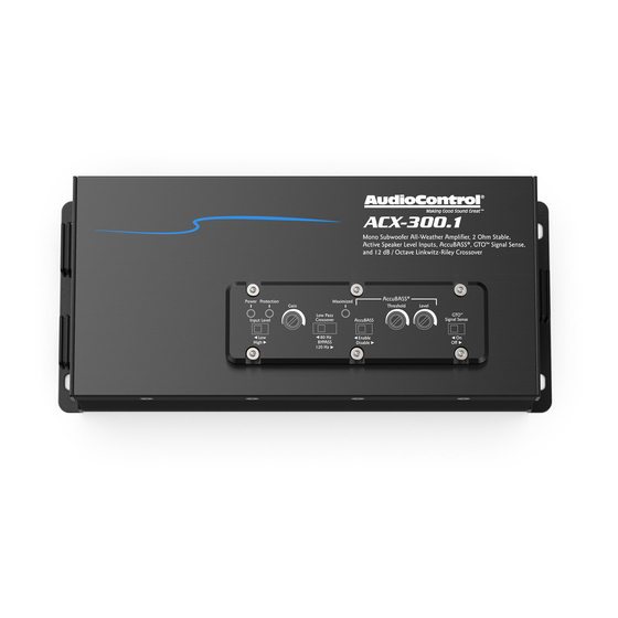
ACX-300.1
INPUT 2
INPUT 1
Quick Start Guide
Advertisement
Table of Contents

Related Manuals for AudioControl ACX-300.1


Summary of Contents for AudioControl ACX-300.1
- Page 1 GTO™ Signal Sense (Great Turn On) • 2 RCA Inputs - switchable for Low and High Level signals • Optional wired ACR-1 Remote Control for Output Level • All-weather rated - IPX6 rated! • Cage-free op-amps ACX-300.1 Quick Start Guide...
-
Page 2: Important Safety Instructions
ACX-300.1 Important Safety Instructions 14. Fuses shall be replaced only with the correct type and fuse value, and Read these instructions. only when the apparatus is powered off. Keep these instructions. 15. Exposure to high sound pressure levels may lead to permanent hearing Heed all warnings. -
Page 3: Connection Features
Connection Features OUTPUT +12V 4 5 6 7 8 9 10 11 12 13 1. Speaker Output – Connect these wires to your subwoofer using 3. Remote Power Input Wire – This wire connects to the 12V remote the included water resistant harness. Speaker wire may then be trigger output of some head units and controls the on/off state of crimped or soldered onto the bare leads. - Page 4 Maximized light shines briefly. This will be your optimal gain Hz, and a “bypass” option. The amplifier reproduces the frequency setting. range below the crossover point. Select the crossover frequency on the ACX-300.1 amplifier to best match the value specified by your loudspeaker’s manufacturer. Quick Start Guide...
-
Page 5: Control Panel Features
12. AccuBASS® Level - Adjusts the level of the AccuBASS® enhance- ment circuitry. 13. GTO ™ Signal Sense – In the ON position, the ACX-300.1 amplifier will turn on gracefully when it detects an incoming audio signal, and it will turn off after a period of time when the audio signal fades away to silence. -
Page 6: Quick Start
Quick Start 7. Connect the +12V input wire on the included wiring harness Here are a few general steps to get your ACX-300.1 amplifier up and assembly to the +12V terminal of the vehicle battery, using the running: appropriate gauge wire 1. - Page 7 Alternatively, the GTO™ Signal Sense feature can INPUT 1 +12V be used to gently turn on the ACX-300.1 amplifier when an audio input signal is detected. (The con- nection to the ACX-300.1 remote input terminal is not required when using the GTO™ signal sense.)
- Page 8 System #1: Using Speaker-Level Inputs ACR-1 Subwoofer Speaker-level output OUTPUT To battery INPUT 2 INPUT 1 +12V +12V 12V Trigger Speaker Level Wires Source Unit...
- Page 9 Cover Plate Removal The cover plate must be removed to gain access to the controls, and then sealed again to protect the controls against moisture and debris. OUTPUT Removal Procedure 1. Locate the top six hex screws that hold down the sealed top cover.
-
Page 10: Specifications
ACX-300.1 Specifications All specifications are measured at 14.4 VDC (standard automotive voltage). As technology advances, AudioControl reserves the right to continuously change our specifications, like our Pacific Northwest weather, although we are working on changing that as well. The ACX-300.1 Amplifier Warranty Power Output (RMS) .
Need help?
Do you have a question about the ACX-300.1 and is the answer not in the manual?
Questions and answers