Table of Contents
Advertisement
Features
•
Compact High Power Mono Subwoofer Amplifier
•
High Current Design
•
1x175 Watts @ 4 Ohm, 1x300 Watts @ 2 Ohm
•
12 dB/Octave Linkwitz-Riley Alignment Crossover
•
GTO™ Signal Sense
•
PFM Subsonic Filter
•
2 Line-Level RCA Inputs, summed
•
2 Active Speaker-Level Inputs, summed
•
AccuBASS® Bass Restoration
•
Filled with home-grown audio goodness
COMPACT HIGH POWER MONO SUBWOOFER AMPLIFIER
Quick Start Guide
Advertisement
Table of Contents

Related Manuals for AudioControl ACM-1.300


Summary of Contents for AudioControl ACM-1.300
- Page 1 Features • Compact High Power Mono Subwoofer Amplifier • High Current Design • 1x175 Watts @ 4 Ohm, 1x300 Watts @ 2 Ohm • 12 dB/Octave Linkwitz-Riley Alignment Crossover • GTO™ Signal Sense • PFM Subsonic Filter • 2 Line-Level RCA Inputs, summed •...
-
Page 2: Important Safety Instructions
10. Provide +12V and Ground wiring of sufficient size to ensure adequate remove the top panel to access the controls. ACM-1.300 There are no user-serviceable parts inside. Refer current to the amplifier. For the this means 8 gauge wire or servicing to qualified personnel. -
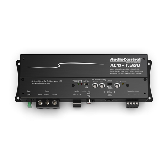
Page 3: Connection Panel Features
Make sure that you follow the plus and minus polarity to the 12V remote trigger output of some head units. When the markings on the ACM-1.300 and match it to the polarity of the head unit is turned on, then the ACM-1.300 amplifier will turn on. - Page 4 Make sure that the average combined speaker impedance does not dip below 2 Ohm. The ACM-1.300 has four connections (2 plus and 2 minus). These four connections allow you to easily add a second subwoofer in parallel, as long as the impedance of both subwoofers is 4 Ohms or greater.
-
Page 5: Control Panel Features
(See the specs page for a list of diagnostic codes.) will begin to work. 10. GTO™ Signal Sense – In the ON position, the ACM-1.300 amplifier AccuBASS® Level – Adjusts the level of the AccuBASS®. will turn on gracefully when it detects an incoming audio signal, and it will turn off after a period of time when the audio signal fades away to silence. - Page 6 14. Gain Maximized LED – This LED indicates when the ACM-1.300 amplifier gain has been maximized for optimum performance. Quick Start Guide...
-
Page 7: Quick Start
Quick Start Here are a few general steps to get your ACM-1.300 amplifier up and 7. Connect the +12V input terminal of the unit to the +12V termi- running: nal of the vehicle battery. Use 8 gauge insulated wire or thicker. -
Page 8: Power Connections
+12V Trigger will turn on the ACM-1.300 amplifier. Alternatively, the GTO™ signal sense feature can be used to gently turn on the ACM-1.300 amplifier when an audio input signal is detected. (The con- nection to the ACM-1.300 remote input terminal is not required when using the GTO™... - Page 9 System #1: Adding a Subwoofer to a Factory Radio using Speaker-Level Inputs Subwoofer Factory Speaker-level Radio outputs Optional lf two subwoofers are connected like this, they are in parallel, and the impedance of each subwoofer must be 4 Ohms or greater. Subwoofer in parallel...
- Page 10 System #2: Adding a Subwoofer to an Aftermarket Head Unit using Line-Level Inputs Subwoofer Aftermarket Line-level L/R outputs Head Unit Optional lf two subwoofers are connected like this, they are in parallel, and the impedance of each subwoofer must be 4 Ohms or greater. Subwoofer in parallel Quick Start Guide...
-
Page 11: Cover Plate Removal
Cover Plate Removal The cover plate must be removed to gain access to the controls, and then put back on again to protect the controls from dust bunnies. Removal Procedure 1. Locate the top four screws that hold the cover plate in place. -
Page 12: Specifications
Specifications All specifications are measured at 14.4 VDC (standard automotive voltage). As technology advances, AudioControl reserves the right to continuously change our specifications, like our Pacific Northwest weather, although we are working on changing that as well. Protection Codes The ACM-1.300 Amplifier The various codes flashed by the Protection LED will help you diagnose any problems with your system.
Need help?
Do you have a question about the ACM-1.300 and is the answer not in the manual?
Questions and answers