Table of Contents
Advertisement
Quick Links
Features
•
Compact High Power 5-Channel Amplifier
•
High Current Design
•
4 x 50 Watts @ 4 Ohms, 1 x 200 Watts @ 4 Ohms
•
4 x 75 Watts @ 2 Ohms, 1 x 350 Watts @ 2 Ohms
•
2 x 150 Watts @ 4 Ohms, Bridged Mono
•
12 dB/Octave Linkwitz-Riley Alignment Crossover
•
GTO™ Signal Sense (Great Turn On)
•
6 Speaker-level/ Line-Level RCA Inputs
•
All-weather IPX6 rated!
•
Filled with home-grown audio goodness
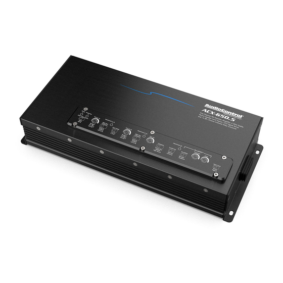
COMPACT HIGH POWER ALL-WEATHER 5-CHANNEL AMPLIFIER
ACX-650.5
Quick Start Guide
Advertisement
Table of Contents

Related Manuals for AudioControl ACX-650.5


Summary of Contents for AudioControl ACX-650.5
- Page 1 2 x 150 Watts @ 4 Ohms, Bridged Mono • 12 dB/Octave Linkwitz-Riley Alignment Crossover • GTO™ Signal Sense (Great Turn On) • 6 Speaker-level/ Line-Level RCA Inputs • All-weather IPX6 rated! • Filled with home-grown audio goodness ACX-650.5 COMPACT HIGH POWER ALL-WEATHER 5-CHANNEL AMPLIFIER Quick Start Guide...
-
Page 2: Important Safety Instructions
ACX-650.5 Important Safety Instructions Read these instructions. 14. Fuses shall be replaced only with the correct type and fuse value, and only when the apparatus is powered off. Keep these instructions. 15. Exposure to high sound pressure levels may lead to permanent hearing Heed all warnings. - Page 3 Connections & Control Panel Features 1. Speaker Outputs – 2. Power Input Terminal +12V & Ground – Connect these wires In Stereo operation, connect one loudspeaker to each channel as to the +12V and Negative binding posts of the vehicle battery shown.
- Page 4 If this lights up, remove the speaker connection and RCA inputs and try again. If error clears, examine 5. GTO™ Signal Sense – In the ON position, the ACX-650.5 amplifier your speaker, speaker wires, and RCAs for possible causes of short.
- Page 5 Pass Crossover for channels 3/4. Set this according to your speaker sound quality. The ACX-650.5 amplifier has selectable high pass manufacturers recommended setting, usually found on the back crossover frequencies at 80 Hz, 120 Hz, and a “bypass” option.
- Page 6 The ACX-650.5 amplifier has selectable crossover frequencies at 80 Hz, 120 Hz, and a “bypass” option. Select the crossover frequency on the ACX-650.5 amplifier to best match the value specified by your loudspeaker’s manufacturer.
-
Page 7: Quick Start
Quick Start Here are a few general steps to get your ACX-650.5 amplifier up and 8. Connect the Ground wire of the power wiring harness assembly running: to a ground source such as the negative battery terminal, vehicle chassis or other ground source, using the same wire gauge as 1. -
Page 8: Power Connections
Power Connections In this example, the head unit has a +12V trigger output that is con- nected to the ACX-650.5 remote input terminal. When the head unit is turned on, it will turn on the ACX-650.5 amplifier. Alternatively, the GTO™ Signal Sense feature can be used to gently turn on the ACX-650.5 amplifier when an audio input signal is detect-... - Page 9 Speaker-Level Outputs (80 Hz and up) Stereo operation, Input Mode: 2 ch, Input Level: High / 2 Ohms minimum per channel To Battery ACR-1 (optional) ACR-1 Cable (included with ACX-650.5) Speaker-level Output (80 Hz and down) Source Unit Speaker-Level Signal Wires...
-
Page 10: Cover Plate Removal
ACX-650.5 Cover Plate Removal The cover plate must be removed to gain access to the controls, and then sealed again to protect the controls against moisture and debris. Removal Procedure 1. Locate the top six hex screws that hold down the sealed top cover. -
Page 11: Specifications
Specifications All specifications are measured at 14.4 VDC (standard automotive voltage). As technology advances, AudioControl reserves the right to continuously change our specifications, like our Pacific Northwest weather, although we are working on changing that as well. The ACX-650.5 Amplifier Warranty Power Output (RMS) . - Page 12 Complimentary Notes page (filled with horizontal lines that may be used for notes, sonnets, poems, shopping lists, and complex crossover equations) ACX-650.5 Quick Start Guide PN 915-033-0 Rev B...
Need help?
Do you have a question about the ACX-650.5 and is the answer not in the manual?
Questions and answers