Table of Contents
Advertisement
Quick Links
Advertisement
Table of Contents

Subscribe to Our Youtube Channel
Related Manuals for Tool Shed TSB03


Summary of Contents for Tool Shed TSB03
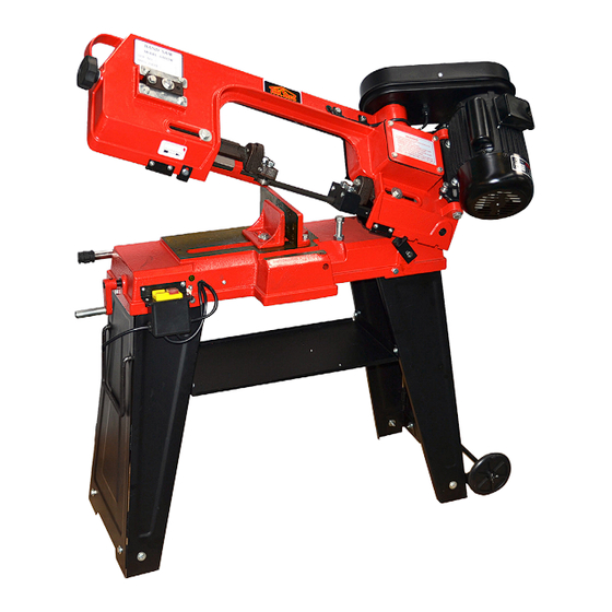
- Page 1 METAL CUTTING BANDSAW TSB03 www.thetoolshed.co.nz...
-
Page 2: Table Of Contents
OPERATION MANUAL OPERATION MANUAL TABLE OF CONTENTS PRODUCT DETAILS Product Details Product Model ToolShed Metal Cutting Bandsaw Specifications Product Identification Product Code TSB03 Safety Guidelines Assembly Operation Maintenance Troubleshooting Exploded Parts List DISTRIBUTED BY: Thank You Note: For the purchase of this ToolShed product. We try our hardest to supply customers like you This manual is for your reference only. -
Page 3: Specifications
OPERATION MANUAL OPERATION MANUAL SPECIFICATIONS PRODUCT IDENTIFICATION 110mm Ø Round Capacity @ 90° 100 x 150mm Square 75mm Ø Round Capacity @ 45° 75 x 100mm Square Speed 20 | 29 | 50m/min Motor Speed 1400 RPM Motor Size 1/2hp | 370 Watts Blades 12.5 x 0.64 x 1638mm Blade Wheels... -
Page 4: Safety Guidelines
OPERATION MANUAL OPERATION MANUAL SAFETY GUIDELINES SAFETY GUIDELINES Electrical Safety Power Tool & Machinery Use & from moving parts in the machine, or they WARNING could become caught therein. Care • DO NOT use the power tool or machinery • Always remain alert and DO NOT operate in rainy conditions or wet areas where the •... - Page 5 OPERATION MANUAL OPERATION MANUAL SAFETY GUIDELINES SAFETY GUIDELINES • Service Bandsaw Specific Safety Work area hazards. Keep the area around or worn parts. Scheduled routine mainte- nance should performed on a scheduled the bandsaw clean from oil, tools, chips. Pay •...
-
Page 6: Assembly
OPERATION MANUAL OPERATION MANUAL ASSEMBLY ASSEMBLY • Before Each Use Fix the other Leg to the Shelf, again, do not fully tighten these screws. • Always inspect your Bandsaw every time. • To reduce the risk of injury from accidental starting, turn the switch off and unplug the bandsaw before changing the set-up, removing covers, guards, or the blade. - Page 7 OPERATION MANUAL OPERATION MANUAL ASSEMBLY ASSEMBLY • Turn the Saw Stand up the right way, pref- erably on a non slip surface. Lift the Saw on top of the Stand with 2 people ensuring the top of the Stand fits inside the Saw Base. Make sure the motor is at the end with the Wheel Bracket.
- Page 8 OPERATION MANUAL OPERATION MANUAL ASSEMBLY ASSEMBLY • • Fit the Motor Pulley, making sure the key is in Fit the Drive Belt. place. Tighten the grub screw. • Feed the wires and the gland through the hole on the underside of the guard. •...
- Page 9 OPERATION MANUAL OPERATION MANUAL ASSEMBLY ASSEMBLY • Fit the Switch Box using the screws shown above. • Screw the 2 Earth wires to the Saw Body as shown above. The correct assembly sequence is; Split Washer against head of • Screw, Flat Washer, 2 Earth wires and lastly Install the two wires to the micro switch (it •...
-
Page 10: Operation
OPERATION MANUAL OPERATION MANUAL OPERATION OPERATION Blade Guide Bearing Changing Speed Blade Selection Loosen the nut while holding the bolt with a Adjustment wrench. • When using your Band Saw, always change Special note: 1x 12.5 x 0.64 x 1638mm 14 TPI Position the eccentric by turning the bolt to the blade speed to best suit the material general use blade is supplied with the metal... -
Page 11: Maintenance
OPERATION MANUAL OPERATION MANUAL OPERATION MAINTENANCE • Changing Blades (Cont.) Adjusting the Blade Tracking Vertical Cutting Plate Assembly Before cleaning or performing any mainte- nance, you must ensure the tool is switched • fingers as guides. This adjustment has been completed and off and disconnected from the power supply. -
Page 12: Troubleshooting
OPERATION MANUAL OPERATION MANUAL TROUBLESHOOTING TROUBLESHOOTING FAULT POSSIBLE CAUSE SUGGESTED SOLUTION FAULT POSSIBLE CAUSE SUGGESTED SOLUTION Material loose in vise Clamp work securely. Tooth too coarse for work Use finer tooth blade. Incorrect speed or feed Adjust speed or feed. Too heavy pressure, too slow speed Decrease pressure, increase speed. -
Page 13: Exploded Parts List
Hex. Head Screw X8 Washer X19 Trans. Wheel Shaft Hex. Nut X11 Hex. Head Screw X2 Key X2 Washer X25 Hex. Head Screw Transmission Gear Floor Stand (Right) Pivot Spring Pin X2 Fixed Plate X4 Vertical Cutting Plate Gear Box Gasket Wheel Assembly X2 Vertical Cut.
Need help?
Do you have a question about the TSB03 and is the answer not in the manual?
Questions and answers