
Related Manuals for Kenwood CK 418


Summary of Contents for Kenwood CK 418
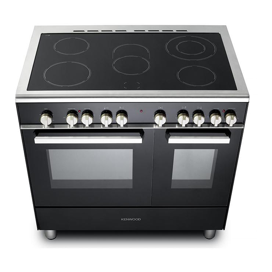
- Page 1 DOUBLE OVEN CERAMIC COOKER CK 418, model CK 418 SL Instructions for use - Installation advice Before operating this cooker, please read these instructions carefully...
-
Page 2: Table Of Contents
CONTENTS Page Number Introduction ..........Important Safety Precautions &... -
Page 3: Introduction
Dear Customer, Thank you for purchasing a Kenwood CK 408-.. double oven gas cooker. The safety precautions and recommendations reported below are for your own safety and that of others. They will also provide a means by which to make full use of the features offered by your appliance. -
Page 4: Important Safety Precautions & Recommendations
IMPORTANT SAFETY PRECAUTIONS AND RECOMMENDATIONS IMPORTANT: This appliance is designed and manufactured solely for the cooking of domestic (household) food and is not suitable for any non domestic application and therefore should not be used in a commercial environment. The appliance guarantee will be void if the appliance is used within a non domestic environment i.e. - Page 5 • Do not operate your appliance by means of an external timer or separate remote-control system. • Do not carry out cleaning or maintenance operations on the appliance without having previously disconnected it from the electric power supply. • WARNING: Ensure that the appliance is switched off before replacing the oven lamp to avoid the possibility of electric shock.
- Page 6 The door is hot, use the handle. – To avoid burns and scalds, young children should be kept – away. • Make sure that electrical cables connecting other appliances in the proximity of the cooker cannot come into contact with the hob or become entrapped in the oven door.
- Page 7 Disconnect the appliance from the electrical power supply, let – the oven cool down and clean the interior of the oven with a cloth soaked in water and neutral detergent; then dry carefully. • CAUTION: Do not use harsh abrasive cleaners or sharp metal scrapers to clean the oven door glass since they can scratch the surface, which may result in shattering of the glass.
- Page 8 ENERGY LABELLING/ECODESIGN • Commission delegated regulation (EU) No 65/2014 (supplementing Directive 2010/30/EU of the European Parliament and of the Council). • Commission regulation (EU) No 66/2014 (implementing Directive 2009/125/EC of the European Parliament and of the Council). Reference to the measurement and calculation methods used to establish compliance with the above requirements: •...
-
Page 11: Advice For The Installer
Advice for the installer... - Page 12 IMPORTANT • Cooker installation and maintenance must only be carried out by QUALIFIED TECHNICIANS and in compliance with the local safety standards. Failure to observe this rule will invalidate the warranty. • The electrical mains outlet, if located behind the cooker, must not be higher than 18 cm above the floor level.
-
Page 13: Installation
1 - INSTALLATION LOCATION The appliance must be kept no less than 50 mm away from any side wall which exceed the height of the hob surface (fig. 1.1). The appliance must be housed in heat resistant units. The walls of the units must be capable of resisting temperatures of 75 °C above room temperature. - Page 14 FITTING THE ADJUSTABLE FEET The adjustable feet must be fitted to the base of the cooker before use. Rest the rear of the cooker on a piece of the polystyrene packag- ing exposing the base for the fit- ting of the feet. Fit the 4 legs by screwing them tight into the support base as Fig.
- Page 15 MOVING THE COOKER WARNING: When raising cooker to upright position always ensure two people carry out this manoeuvre to prevent damage to the adjustable feet (fig. 1.5). Fig. 1.5 WARNING WARNING Be carefull: Do not lift the cooker by When moving cooker to its final position the door handle/s when raising to the DO NOT DRAG (fig.
- Page 16 ANTI-TILT BRACKET Important! To restrain the appliance and prevent it tipping accidentally, fit a bracket to its rear to fix it securely to the wall. To fit the anti-tilt bracket: After you have located where the cooker is to be positioned, mark on the wall the place where the two screws of the anti-tilt bracket have to be fitted.
-
Page 17: Electrical Installation
2 - ELECTRICAL INSTALLATION N.B. For connection to the mains, do IMPORTANT: The cooker must be not use adapters, reducers or branching installed accordance with devices as they can cause overheating manufacturer’s instructions. and burning. Incorrect installation, which manufacturer accepts If the installation requires alterations to the responsibility, may cause damage to domestic electrical system, call an expert. - Page 18 CONNECTION OF THE POWER FEEDER CABLE SECTION SUPPLY CABLE TYPE H05RR-F or H05VV-F Connecting power cord must 230 V ac 3 x 6 mm (**) entrusted skilled personnel 400 V 3N ac 5 x 2,5 mm (**) in accordance with the instructions 400 V 2N ac 4 x 4 mm (**)
- Page 19 230 V~ N (L2) 1 2 3 4 5 230 V~ N (L 400 V 3N~ 1 2 3 4 5 400 V 3N~ 400 V 2N~ 1 2 3 4 5 400 V 2N~ Fig. 2.3 Fig. 2.2...
-
Page 21: Advice For The Users
Advice for users... -
Page 22: Cooking Hob
1 - COOKING HOB Fig. 1.1 VITROCERAMIC COOKING HOB “Hi-Light” single zone, Ø 180 mm 1800 W “Hi-Light” single zone, Ø 145 mm 1200 W “Hi-Light” double zone (oval), Ø 145 x 250 mm 2000/1100 W “Hi-Light” double zone, Ø 210/120 mm 2200/750 W “Hi-Light”... -
Page 23: Control Panel
2 - CONTROL PANEL Fig. 2.1 CONTROL PANEL - Controls description Front right cooking zone control knob Rear right cooking zone control knob Central cooking zone control knob Rear left cooking zone control knob Front left cooking zone control knob Fan main oven switch knob Fan main oven temperature knob 120 minutes timer control knob... -
Page 24: Use Of Cooking Hob
3 - USE OF COOKING HOB The ceramic surface of the hob allows a fast transmission of heat in the vertical direction, from the heating elements underneath the ceramic glass to the pans set on it. The heat does not spread in a horizontal direction, so that the glass stays “cool” at only a few centimeters from the cooking plate. - Page 25 “HI-LIGHT” DOUBLE ZONES (figs. 3.4, 3.5) • The heating element is formed of 2 coils of resistant material which reaches the working temperature quickly. • This zone is controlled by a continuous energy regulator switch (fig. 3.3). The heat intensity can be regulated continuously from “0” to “12” (max). •...
- Page 26 COOKING HINTS Cooking zone controlled by a Knob TYPE OF COOKING 12 position setting energy regulator Switched OFF melting operations (butter, chocolate). To maintain food hot and to heat small quantities of liquid (sauces, eggs). To heat bigger quantities; to whip creams and sauces (vegetables, fruits, soups).
- Page 27 RESIDUAL HEAT INDICATOR Caution! The hob also features no. 5 (five) The cooking hob becomes very hot warning lights which are connected to the during operation. corresponding plates. Keep children well out of reach. When the temperature of a cooking plate is above 60°C, the relevant warning light will COOKING HINTS: also light up to warn of heat on the surface...
- Page 28 ADVICE FOR SAFE USE OF THE CLEANING COOKTOP Before you begin cleaning make sure • Before switching on make sure that that the appliance is switched off. you have the correct knob for the Remove any encrustation using a scraper hotplate chosen.
-
Page 29: Fan Main Oven
4 - FAN MAIN OVEN OPERATING PRINCIPLES Attention: the oven door becomes Heating and cooking in the FAN oven are very hot during operation. obtained in the following ways: Keep children away. a. by forced convection A fan sucks in the air contained in the oven muffle, which sends it through the circular heating element and then GENERAL FEATURES... - Page 30 Fig. 4.1 Fig. 4.2 TEMPERATURE KNOB (fig. 4.1) To turn on the heating elements of the oven, set the switch knob on the desired program and select the required temperature. To set the temperature, line up the temperature knob indicator with the required temperature.
- Page 31 HOT AIR COOKING The circular element and the fan are on. The heat is diffused by forced convection and the temperature must be regulated between 50° and 250 °C with the ther mostat knob. It is not necessary to preheat the oven. Recommended for: For foods that must be well done on the outside and tender or rare on the inside, i.
- Page 32 COOKING ADVICE SIMULTANEOUS COOKING STERILIZATION DIFFERENT FOODS Sterilization of foods to be conserved, in The FAN consents a simultaneous he- full and hermetically sealed jars, is done in terogeneous cooking of different foods. the following way: Different foods such as fish, cake and meat can be cooked together without a.
-
Page 33: Conventional Oven
5 - CONVENTIONAL OVEN OPERATING PRINCIPLES Attention: the oven door becomes Heating cooking very hot during operation. CONVENTIONAL oven are obtained in the Keep children away. following ways: a. by natural convection GENERAL FEATURES The heat is produced by the upper and The conventional oven has 3 heating ele- lower heating elements. - Page 34 OVEN LIGHT By setting the knob to this position, only the oven light comes on. It remains on in all the cooking modes. ECO FUNCTION (ENERGY SAVING) The upper and lower heating elements are switched on. The heat is diffused by natural convection.
-
Page 35: Oven Temperature Guide
6 - OVEN TEMPERATURE GUIDE Electric oven temperature Cooking process Oven heat Gas mark °C °F Keeping food hot, ½ very cool milk puddings Egg custards cool Rich fruit cakes, cool braising Low temperature moderate roasting, shortbread Victoria sandwich, plain fruit cake, moderate baked fish Small cakes, choux... -
Page 36: 120 Minutes Timer
7 - 120 MINUTES TIMER 120 MINUTES TIMER fig. 7.1) The timer can be set to a maximum of 120 minutes and a buzzer will sound at the end of the countdown. The knob must be rotated clockwise as far as the 120 minutes position first and then set to the required time by rotating it anticlockwise. -
Page 37: Cleaning & Maintenance
8 - CLEANING AND MAINTENANCE WARNING! GENERAL ADVICE When correctly installed, your product Before you begin cleaning, you • meets all safety requirements laid must ensure that the appliance is down for this type of product category. switched off and disconnected from the electrical power supply. - Page 38 INSIDE OF OVEN Fig. 8.1 The oven should always be cleaned after use when it has cooled down. The bottom of the oven, side runner frames, tray and rack can be removed and washed. The cavity should be cleaned using a mild detergent solution and warm water.
- Page 39 STORAGE COMPARTMENT The storage compartment is accessible through the pivoting panel (fig. 8.3). Do not store flammable material in the oven or in the storage compartment. Attention: The oven door becomes very hot during operation. Keep children away. Fig. 8.3 OVEN DOORS The internal glass panel can be easily removed for cleaning by unscrewing the retaining screws (fig.
- Page 40 REPLACING THE OVEN LAMP WARNING: Ensure the appliance is switched off and disconnected from the electrical power supply before replacing the lamp to avoid the possibility of WRONG electric shock. • Let the oven cavity and the heating elements cool down. •...
- Page 41 REMOVING THE OVEN DOOR The oven door can easily be removed as follows: • Open the door to the full extent (fig. 8.6a). • Open the lever “A” completely on the left and right hinges (fig. 8.6b). • Hold the door as shown in fig. 8.6. •...
- Page 42 9 - GUARANTEE Your new “KENWOOD” product comes with 12-month guarantee covering all parts and labour. If your appliance proves to be defective as a result of faulty materials or workmanship during the guarantee period, these parts will be repaired or replaced free of charge.
- Page 44 The manufacturer cannot be held responsible for possible inaccuracies due to printing or transcription errors in the present booklet. The manufacturer reserves the right to make all modifications to its products deemed necessary for manufacture or commercial reasons at any moment and without prior notice, without jeopardising the essential functional and safety characteristics of the appliances.
Need help?
Do you have a question about the CK 418 and is the answer not in the manual?
Questions and answers