
Related Manuals for Rohde & Schwarz R&S FE170ST


Summary of Contents for Rohde & Schwarz R&S FE170ST
- Page 1 ® R&S FE170ST / ® R&S FE170SR External Frontends Manual (;ÝÆÊ2) 1179566002 Version 02...
- Page 2 This document describes the following FE170-type external frontends: ● R&S ® FE170ST (1347.9190K02) ● R&S ® FE170SR (1347.9090K02) Available external devices: ● R&S ® FE170-Z01 BP-Filter 110 - 136 GHz (1347.9532.02) ● R&S ® FE170-Z02 BP-Filter 126 - 153 GHz (1347.9549.02) ●...
-
Page 3: Table Of Contents
® ® Contents R&S FE170ST / R&S FE170SR Contents 1 Safety information (multilingual)..........5 2 About the external frontend..........10 3 Unpacking and checking............ 14 4 Setting up the external frontend........15 5 Connecting the external frontend........16 6 External frontend tour............26 7 Contacting customer support.......... - Page 4 ® ® Contents R&S FE170ST / R&S FE170SR Manual 1179.5660.02 ─ 02...
-
Page 5: Safety Information (Multilingual)
® ® Safety information (multilingual) R&S FE170ST / R&S FE170SR Safety information (multilingual) This option or accessory is designed for a specific Rohde & Schwarz prod- uct. Multilingual safety information is delivered with the product. Follow the provi- ded installation instructions. Esta opción o este accesorio están diseñados para un producto Rohde &... - Page 6 ® ® Safety information (multilingual) R&S FE170ST / R&S FE170SR Detta tillval eller tillbehör är avsett för en särskild produkt från Rohde & Schwarz. Säkerhetsinformation på flera språk medföljer produkten. Följ de medföljande installationsanvisningarna. Tämä vaihtoehto tai lisävaruste on suunniteltu tietylle Rohde & Schwarz -yrityk- sen tuotteelle.
- Page 7 ® ® Safety information (multilingual) R&S FE170ST / R&S FE170SR Tato varianta nebo příslušenství je určeno pro konkrétní produkt Rohde & Schwarz. S produktem jsou dodávány vícejazyčné bezpečnostní infor- mace. Řiďte se přiloženými pokyny k instalaci. Táto verzia alebo príslušenstvo je navrhnutá pre špecifický výrobok Rohde &...
- Page 8 ® ® Safety information (multilingual) R&S FE170ST / R&S FE170SR Bu opsiyon veya aksesuar, belirli bir Rohde & Schwarz ürünü için tasarlanmış- tır. Çok dilli güvenlik uyarıları ürünle birlikte teslim edilir. Size sağlanan kurulum talimatlarına uyun. Şu opsiýa ýa-da esbap Rohde & Schwarz anyk önüm üçin niýetlenilen. Dürli dil- däki howpsuzlyk barada maglumat önüm bilen bile üpjün edilýär.
- Page 9 ® ® Safety information (multilingual) R&S FE170ST / R&S FE170SR Esta opção ou acessório foi desenvolvido para um produto Rohde & Schwarz específico. Informações de segurança em vários idiomas acompanham o pro- duto. Siga as instruções de instalação disponibilizadas. Manual 1179.5660.02 ─ 02...
-
Page 10: About The External Frontend
® ® About the external frontend R&S FE170ST / R&S FE170SR Key features R&S FE170ST About the external frontend Intended use The FE170-type external frontend (FE) is intended as an accessory for various control instruments, e.g. a Rohde & Schwarz vector signal generator. Observe the operating conditions and performance limits stated in the data sheet. - Page 11 ® ® About the external frontend R&S FE170ST / R&S FE170SR Documentation overview Key features R&S FE170SR ● Frequency down-conversion for D-band signals (110 GHz to 170 GHz) ● Up to 8.3 GHz analysis bandwidth ● RF connector with input peak envelope power (PEP) of -100 dBm to +15 dBm ●...
- Page 12 ® ® About the external frontend R&S FE170ST / R&S FE170SR Documentation overview 2.3.3 Related documentation Frontend control documentation To find out how to use the FE170-type external frontend in setups with this control instrument, see ● Frontend control user manual of the control instrument ●...
- Page 13 ® ® About the external frontend R&S FE170ST / R&S FE170SR Korea certification class A Korea certification class A 이 기기는 업무용(A급) 전자파 적합기기로서 판매자 또는 사용자는 이 점을 주의하 시기 바라며, 가정외의 지역에서 사용하는 것을 목적으로 합니다. Manual 1179.5660.02 ─ 02...
-
Page 14: Unpacking And Checking
® ® Unpacking and checking R&S FE170ST / R&S FE170SR Unpacking and checking 1. Unpack the FE170-type external frontend carefully. 2. Retain the original packing material. Use it when transporting or shipping the FE170-type external frontend later. 3. Using the delivery notes, check the equipment for completeness. 4. -
Page 15: Setting Up The External Frontend
® ® Setting up the external frontend R&S FE170ST / R&S FE170SR Setting up the external frontend The FE170-type external frontend is used exclusively in test setups with a control instrument, e.g. the R&S SMW200A. To place the FE170-type external frontend on a bench top 1. -
Page 16: Connecting The External Frontend
® ® Connecting the external frontend R&S FE170ST / R&S FE170SR Considerations for test setup Connecting the external frontend When connecting the FE170-type external frontend in your test setup, use the cables provided with the delivery. Considerations for test setup Cable selection and electromagnetic interference (EMI) Electromagnetic interference (EMI) can affect the measurement results. - Page 17 ® ® Connecting the external frontend R&S FE170ST / R&S FE170SR Connecting to power b) Use a conductive floor mat and heel strap combination. To block DC components ► NOTICE! Excessive DC voltage at the RF input connector can damage the instrument.
- Page 18 ® ® Connecting the external frontend R&S FE170ST / R&S FE170SR Connecting to LAN 2. Switch on the FE170-type external frontend. How to: Chapter 5.7, "Switching on or off", on page 24 If hardware problems persist, contact Rohde & Schwarz customer support. Status LEDs Status LEDs indicate the power and LAN state.
- Page 19 ® ® Connecting the external frontend R&S FE170ST / R&S FE170SR Connecting to the waveguide connector plays the IP address information on the electronic label with "IP Addr.:". See Chapter 6.3, "Electronic label", on page 32. ● If the network does not support DHCP or the attempt does not succeed, the external frontend tries to obtain the IP address via Zeroconf (APIPA) protocol.
- Page 20 ® ® Connecting the external frontend R&S FE170ST / R&S FE170SR Connecting to SMA and 2.92 mm connectors 3. Carefully align the pins to the holes of the WR-6.5 waveguide connectors on the DUT to the holes of the connector on the FE170-type external frontend until they match.
- Page 21 ® ® Connecting the external frontend R&S FE170ST / R&S FE170SR Connecting to a control instrument 2. NOTICE! Excessive reverse power at the RF connector can damage the instrument. Make sure that the signal power is within the limits as given in the data sheet. 3.
- Page 22 ® ® Connecting the external frontend R&S FE170ST / R&S FE170SR Connecting to a control instrument How to: Chapter 5.5, "Connecting to SMA and 2.92 mm connectors", on page 20. 5.6.1 Test setup with R&S FE170ST Test setup with an external frontend connected to a vector signal generator as control instrument and an antenna, which is mounted inside an RF shield box.
- Page 23 ® ® Connecting the external frontend R&S FE170ST / R&S FE170SR Connecting to a control instrument Recommended frequency ranges for external filters The supported frequency ranges of the available external filters overlap. For best results regarding image suppression and LO feedthrough, for example, use the filter according to the frequency range listed in Table 5-4.
- Page 24 ® ® Connecting the external frontend R&S FE170ST / R&S FE170SR Switching on or off 5.6.3.2 To connect external devices to the R&S FE170SR Test setup RF shield box RF In RF In IF Out R&S Band- Preamp. Signal Analyzer FE170SR filter Figure 5-5: R&S FE170SR with additional external devices (signal analyzer as control...
- Page 25 ® ® Connecting the external frontend R&S FE170ST / R&S FE170SR Switching on or off To switch on the FE170-type external frontend manually The FE170-type external frontend is switched off, but connected to power. The "Power" LED is gray. See Table 5-1.
-
Page 26: External Frontend Tour
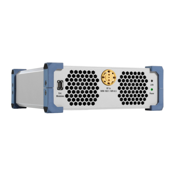
® ® External frontend tour R&S FE170ST / R&S FE170SR Front panel tour External frontend tour This chapter provides an overview of the control elements and connectors of the FE170-type external frontend. The meanings of the labels on the FE170-type external frontend are described in Chapter 6.3, "Electronic label", on page 32. - Page 27 ® ® External frontend tour R&S FE170ST / R&S FE170SR Front panel tour R&S FE170SR front panel Figure 6-2: R&S FE170SR front panel IX type B connector RF Out / RF In connector LAN status LED Power status LED 6.1.1 IX type B connector The IX type B connector allows you to connect external devices to the FE170- type external frontend.
- Page 28 ® ® External frontend tour R&S FE170ST / R&S FE170SR Rear panel tour 6.1.2 RF Out / RF In connector The "RF Out" (R&S FE170ST) or "RF In" (R&S FE170SR) connector is a WR-6.5 waveguide connector for RF signal output or RF signal input in a frequency range of 110 GHz to 170 GHz.
- Page 29 ® ® External frontend tour R&S FE170ST / R&S FE170SR Rear panel tour Rear panel (R&S FE170ST) Figure 6-3: R&S FE170ST rear panel IF connector No Signal connector (R&S FE170ST) Ref In connector 4, 5 = LO In/LO Out connector USB In connector Power supply connector LAN connector...
- Page 30 ® ® External frontend tour R&S FE170ST / R&S FE170SR Rear panel tour IF connector Ref In connector 3, 4 = LO In/LO Out connector USB In connector Power supply connector LAN connector IP Preset button Power key 6.2.1 IF connector Female 2.92 mm connector for input of the intermediate frequency (IF) signal from the control instrument (R&S FE170ST) or to output the intermediate fre- quency (IF) signal to the control instrument (R&S FE170SR).
- Page 31 ® ® External frontend tour R&S FE170ST / R&S FE170SR Rear panel tour 6.2.6 Power supply connector Main power supply connector for connection of the external DC power supply. How to: Chapter 5.2, "Connecting to power", on page 17 6.2.7 LAN connector RJ-45 connector to connect the FE170-type external frontend to a LAN.
- Page 32 ® ® External frontend tour R&S FE170ST / R&S FE170SR Electronic label Electronic label The electronic label is located on the right side panel of the frontend casing. If connected to a LAN, it displays specific network parameters, see Table 6-1.
-
Page 33: Contacting Customer Support
® ® Contacting customer support R&S FE170ST / R&S FE170SR Contacting customer support Technical support – where and when you need it For quick, expert help with any Rohde & Schwarz product, contact our customer support center. A team of highly qualified engineers provides support and works with you to find a solution to your query on any aspect of the operation, program- ming or applications of Rohde &... -
Page 34: Index
® ® Index R&S FE170ST / R&S FE170SR Index Checking the instrument ......14 Connecting IP Preset ..........31 Control instrument ......21 Power ..........31 LAN ............. 18 Key features ........10, 11 Power ..........17 To 2.92 mm ......... 20 To IF ............ 20 To REF ..........
Need help?
Do you have a question about the R&S FE170ST and is the answer not in the manual?
Questions and answers