SOLIS S5 Series Installation And Operation Manual
Three phase inverter
Hide thumbs
Also See for S5 Series:
- User manual ,
- Installation and operation manual (28 pages) ,
- Instructions (5 pages)
Table of Contents
Advertisement
Quick Links
Ginlong Technologies Co., Ltd.
No. 57 Jintong Road, Binhai Industrial Park, Xiangshan, Ningbo,
Zhejiang, 315712, P.R.China.
Tel: +86 (0)574 6578 1806
Fax: +86 (0)574 6578 1606
Please adhere to the actual products in case of any discrepancies in this user manual.
If you encounter any problem on the inverter, please find out the inverter S/N
and contact us, we will try to respond to your question ASAP.
Solis S5 Three Phase Inverter
5K to 13K Installation and Operation Manual
Ginlong Technologies Co., Ltd.
(For Australia)
Ver 1.2
Advertisement
Table of Contents

Related Manuals for SOLIS S5 Series


Summary of Contents for SOLIS S5 Series
- Page 1 Solis S5 Three Phase Inverter 5K to 13K Installation and Operation Manual (For Australia) Ver 1.2 Ginlong Technologies Co., Ltd. No. 57 Jintong Road, Binhai Industrial Park, Xiangshan, Ningbo, Zhejiang, 315712, P.R.China. Tel: +86 (0)574 6578 1806 Fax: +86 (0)574 6578 1606 Please adhere to the actual products in case of any discrepancies in this user manual.
-
Page 2: Table Of Contents
Contents 1. Introduction …………………………………………………………………………………………………………………………… 1.1 Product Description ………………………………………………………………………………………………………… 1.2 Packaging ………………………………………………………………………………………………………………………… 2. Safety Instructions …………………………………………………………………………………………………………… 2.1 Safety Symbols ………………………………………………………………………………………………………………… 2.2 General Safety Instructions …………………………………………………………………………………………… 2.3 Notice For Use ………………………………………………………………………………………………………………… 2.4 Notice for Disposal ………………………………………………………………………………………………………………… 3. Overview ……………………………………………………………………………………………………………………………… 3.1 Front Panel Display ………………………………………………………………………………………………………... -
Page 3: Introduction
1. Introduction 1.2 Packaging 1.1 Product Description Solis S5 three phase inverters integrate DRM and backflow power control function, When you receive the inverter, please ensure that all the parts listed below are included: that is suitable for smart grid requirement. -
Page 4: Safety Instructions
AS/NZS 4777.1. with the NEC Article 690, Part II. All Solis three phase inverters feature an integrated DC switch. 2.4 Notice for Disposal CAUTION: This product shall not be disposed of with household waste. -
Page 5: Overview
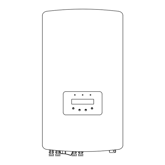
3. Overview 4. Product handing and storage 3.1 Front Panel Display 4.1 Product handling Please review the instruction below for handling the inverter: 1 The red circles below denote cutouts on the product package. Push in the cutouts to form handles for moving the inverter (see Figure 4.1). Figure 3.1 Front Panel Display 3.2 LED Status Indicator Lights Figure 4.1 move the inverter... -
Page 6: Product Storage
4. Product handing and storage 5. Installation 4.2 Product Storage 5.1 Select a Location for the Inverter If the inverter is not to be installed immediately, storage instructions and environmental To select a location for the inverter, the following criteria should be considered: conditions are below: WARNING: Risk of fire Use the original box to repackage the inverter, seal with adhesive tape with the... -
Page 7: Mounting The Inverter
5. Installation 5. Installation 5.2 Mounting the Inverter ≤15° Dimensions of mounting bracket: √ √ Vertical Backward Inverted × × Figure 5.3 Inverter wall mounting Refer to figure 5.4 and figure 5.5. Inverter shall be mounted vertically. The steps to mount the inverter are listed below. The visibility of LED status indicator lights and LCD should be considered. -
Page 8: Electrical Connections
5. Installation 5. Installation 5. Anti-theft lock mount(optional) Anti-theft lock( User-supplied) function is that inverter is fixed in bracket in case theft. WARNING: The lock is selected by 5mm(the keyhole diameter), and the lock of stainless steel is The inverter must be mounted vertically. preferred. - Page 9 5. Installation 5. Installation 5.3.1 Grounding To effectively protect the inverter, two grounding methods must be performed. Connect the AC grounding cable (Please refer to section 5.3.3). Connect the external grounding terminal. To connect the grounding terminal on the heat sink, please follow the steps below: ≥...
- Page 10 5. Installation 5. Installation 5.3.2 Connect PV side of inverter 5. Measure PV voltage of DC input with multimeter, verify DC input cable polar (see figure 5.17), and ensure each string of PV voltage in range of inverter operation. Before connecting inverter, please make sure the PV array open circuit Connect DC connector with inverter until hearing a slight clicking sound indicates voltage is within the limit of the inverter.
- Page 11 5. Installation 5. Installation 5.3.3 Connect grid side of inverter The steps of AC grid terminal connector for installation are as follows: For all AC connectors, YJV-0.6/1kV cables with 6mm² diameter are required to be used. Please make sure the resistance of AC cable is lower than 1.5 ohm. A) Fix the wires into the correct position and the torque is 0.8N.m Please try to pull out the wire slightly to make sure that the wires are well connected.
- Page 12 Table 5.2 Rating of grid OCPD 21 22 1718 19 20 5.3.5 Inverter monitoring connection The inverter can be monitored via Wi-Fi or GPRS. All Solis communication devices are optional (Figure 5.25). For connection instructions, please refer to the Solis Monitoring L2' L3 2-Pin Connector Device installation manuals.
- Page 13 21 22 17 1819 20 against any potential d.c component and a.c component of residual current. Therefore, all Solis inverters, due to the design, are not able to feed in DC fault current to the system which fully complies with IEC60364-7-712.
-
Page 14: Start & Stop
5.3.9 Earth Fault Alarm the LED's are OFF, operators must wait five (5) minutes after the DC power Solis inverters fully comply with IEC62109-2 in terms of earth fault alarm (PV insulation source has been disconnected before opening the inverter cabinet. DC detection and protection). -
Page 15: Operation
7.2 Information 7.2.1 Lock screen The Solis three Phase S5 Inverter main menu provides access to operational data and Pressing the ESC key returns to the Main Menu. Pressing the ENTER key locks information. The information is displayed by selecting "Information" from the menu (Figure 7.2(a)) or unlocks (Figure 7.2 (b)) the screen. -
Page 16: Settings
This function is used to set the address when muti inverters are connected to three monitor. 4. Daily Energy The address number can be assigned from “01”to “99”(see Figure 7.4). The default address 5. Monthly Energy number of Solis Three Phase Inverter is “01”. 6. Yearly Energy 7. Daily Record YES=<ENT> NO=<ESC>... - Page 17 7. Operation 7. Operation 7.4.2 Running Message 7.4.5 Monthly Energy The function is for checking the energy generation for selected month. This function is for maintaince person to get running message such as internal temperature, Standard No.1,2,etc. Screens can be scrolled manually by pressing the UP/DOWN keys. YES=<ENT>...
-
Page 18: Advanced Settings
7. Operation 7. Operation 7.4.7 Daily Record 7.5 Advanced Settings - Technicians Only The screen shows history of changing settings. Only for maintance personel. NOTE: 7.4.8 Communication Data To access to this area is for fully qualified and accredited technicians only. Please follow 7.4 to enter password to access this menu. - Page 19 7. Operation 7. Operation 7.5.2 Grid ON/OFF This function is used to start up or stop the power generation of Solis Three Phase NOTE: Inverter. For different countries, the grid standard needs to be set as different according to local requirements. If there is any doubt, please consult Grid ON Solis service technicians for details.
- Page 20 4. Rea_P With Restore 5. Select PF Curve 7.5.9.1 Working Mode Set Solis AU version inverters have the following working mode settings: This function is applicable by maintenance personnel only, wrong operation 1. NULL will prevent the inverter from reaching maximum power.
- Page 21 7. Operation 7. Operation Supplying Inverter Voltage,V Figure 7.23 Status: Enable/Disable (Note: This is used to enable or disable the Volt-Watt mode) Voltage 1: 207V P-Limit 1: 100% Voltage 2: 220V Absorbing P-Limit 2: 100% Inverter Voltage, V Voltage 3 (Vw1): 235-255V (Default: 4777-A(253V);...
- Page 22 Inverters can work with a smart meter to monitor the load consumption data for the whole day and the data will be displayed on the Solis monitoring system. “DRM ON/OFF” is used to enabled or disable the functionality of the DRM port.
- Page 23 Meter in Load: Solis Smart Meter is connected in the load branch circuit. connection is lost during operation. Meter in Grid: Solis Smart Meter is connected in the grid connection point (The backflow It can prevent potential backflow power into the grid when the system loses control.
- Page 24 ->Backflow Work Mode Figure 7.33 Figure 7.30 Set the Backflow work mode 7.5.13 External EPM Set This setting should only be turned on when Solis external EPM device is used. YES=<ENT> NO=<ESC> Two options are available:5G-EPM and Others-EPM. Mode:01 Figure 7.31 ->5G-EPM...
-
Page 25: Afci Function
Once the DC circuit issue has been fixed or it is confirmed to be OK, press “ESC” for 3s and wait for the inverter to restart. Solis inverters have the built-in AFCI function which can detect the arc fault on the DC circuit and shut down the inverter to prevent a fire disaster. -
Page 26: Maintenance
8. Maintenance 9. Troubleshooting Solis Three Phase Inverter does not require any regular maintenance. However, cleaning The inverter is designed in accordance with the most important international grid-tied the dust on heat-sink will help the inverter to dissipate the heat and increase its life time. - Page 27 Please keep ready with you the following information before contacting us. 1. Serial number of Solis Three Phase Inverter; 2. The distributor/dealer of Solis Three Phase Inverter (if available); 3. Installation date. 4. The description of problem (i.e. the alarm message displayed on the LCD and the status of the LED status indicator lights.
-
Page 28: Specifications
10. Specifications 10. Specifications Model S5-GR3P5K-AU Model S5-GR3P5K-AU Max. DC input voltage (Volts) Max inverter backfeed current to array (Amps) 1100 Rated DC voltage (Volts) Peak Inrush current (Amps) 0.79 Start-up voltage (Volts) Peak Inrush Duration (ms) MPPT voltage range (Volts) Max output fault current (Amps) 160...1000 9.875... - Page 29 10. Specifications 10. Specifications Model S5-GR3P6K-AU Model S5-GR3P6K-AU Max. DC input voltage (Volts) Max inverter backfeed current to array (Amps) 1100 Rated DC voltage (Volts) Peak Inrush current (Amps) 0.95 Start-up voltage (Volts) Peak Inrush Duration (ms) MPPT voltage range (Volts) Max output fault current (Amps) 160...1000 11.875...
- Page 30 10. Specifications 10. Specifications Model S5-GR3P8K-AU Model S5-GR3P8K-AU Max. DC input voltage (Volts) Max inverter backfeed current to array (Amps) 1100 Rated DC voltage (Volts) Peak Inrush current (Amps) 1.27 Start-up voltage (Volts) Peak Inrush Duration (ms) MPPT voltage range (Volts) Max output fault current (Amps) 160...1000 15.875...
- Page 31 10. Specifications 10. Specifications Model S5-GR3P9K-AU Model S5-GR3P9K-AU Max. DC input voltage (Volts) Max inverter backfeed current to array (Amps) 1100 Rated DC voltage (Volts) Peak Inrush current (Amps) 1.43 Start-up voltage (Volts) Peak Inrush Duration (ms) MPPT voltage range (Volts) Max output fault current (Amps) 160...1000 17.875...
- Page 32 10. Specifications 10. Specifications Model S5-GR3P10K-AU Model S5-GR3P10K-AU Max. DC input voltage (Volts) Max inverter backfeed current to array (Amps) 1100 Rated DC voltage (Volts) Peak Inrush current (Amps) 1.59 Start-up voltage (Volts) Peak Inrush Duration (ms) MPPT voltage range (Volts) Max output fault current (Amps) 160...1000 19.875...
- Page 33 10. Specifications 10. Specifications Model S5-GR3P12K Model S5-GR3P12K Max. DC input voltage (Volts) Max inverter backfeed current to array (Amps) 1100 Rated DC voltage (Volts) Peak Inrush current (Amps) 1.91 Start-up voltage (Volts) Peak Inrush Duration (ms) MPPT voltage range (Volts) Max output fault current (Amps) 160...1000 23.875...
- Page 34 10. Specifications 10. Specifications Model S5-GR3P13K Model S5-GR3P13K Max. DC input voltage (Volts) Max inverter backfeed current to array (Amps) 1100 Rated DC voltage (Volts) Peak Inrush current (Amps) 2.07 Start-up voltage (Volts) Peak Inrush Duration (ms) MPPT voltage range (Volts) Max output fault current (Amps) 160...1000 25.875...
-
Page 35: Appendix
11. Appendix 11.1 Built-In DC Isolator Specification Model GHX6-55P NDG3V-50 Rated insulation voltage 1500V Rated impulse withstand voltage 8000V Suitability for isolation Suitable for isolation Rated operational current 45A at 1100V 40A at 1100V Utilization category DC-PV2 Rated short-time withstand current(Icw) 1500A 700A Rated short-circuit making capacity(Icm)
Need help?
Do you have a question about the S5 Series and is the answer not in the manual?
Questions and answers