Table of Contents
Advertisement
Quick Links
Advertisement
Table of Contents

Subscribe to Our Youtube Channel
Related Manuals for IFM Electronic efector500 PI299 Series


Summary of Contents for IFM Electronic efector500 PI299 Series
- Page 1 Operating instructions Electronic pressure sensor PI299x...
-
Page 2: Table Of Contents
Contents 1 Preliminary note ���������������������������������������������������������������������������������������������������3 1�1 Symbols used ������������������������������������������������������������������������������������������������3 2 Safety instructions �����������������������������������������������������������������������������������������������3 3 Functions and features ����������������������������������������������������������������������������������������4 3�1 Applications ���������������������������������������������������������������������������������������������������4 4 Function ���������������������������������������������������������������������������������������������������������������4 4�1 Processing of the measured signals ��������������������������������������������������������������4 4�2 Pressure monitoring / switching function �������������������������������������������������������5 4�3 Pressure monitoring/ analogue function ��������������������������������������������������������5 4�4 Diagnostic function ����������������������������������������������������������������������������������������7 5 Installation������������������������������������������������������������������������������������������������������������8 6 Electrical connection ������������������������������������������������������������������������������������������10... -
Page 3: Preliminary Note
10 Operation ���������������������������������������������������������������������������������������������������������20 10�1 Read the set parameter values �����������������������������������������������������������������20 10�2 Fault indication ������������������������������������������������������������������������������������������20 10�3 Cleaning of the filter cover �������������������������������������������������������������������������21 11 Scale drawing �������������������������������������������������������������������������������������������������22 12 Technical data ��������������������������������������������������������������������������������������������������22 12�1 Setting ranges �������������������������������������������������������������������������������������������24 13 Factory setting �������������������������������������������������������������������������������������������������25 1 Preliminary note 1.1 Symbols used ►... -
Page 4: Functions And Features
3 Functions and features The pressure sensor detects the system pressure of machines and installations� 3.1 Applications Type of pressure: relative pressure Permissible Order no. Measuring range Bursting pressure overload pressure PI2993 -1���25 -14�4���362�7 1 450 2 900 PI2994 -1���10 -14�5���145 2 175 PI2995... -
Page 5: 4�2 Pressure Monitoring / Switching Function
4.2 Pressure monitoring / switching function OUT1 changes its switching state if it is above or below the set switching limits (SP1, rP1)� The following switching functions can be selected: • Hysteresis function / normally open: [OU1] = [Hno] (→ fig. 1). •... - Page 6 • By teaching the analogue end point (tAEP) or setting the parameter AEP you define the measured value at which the output signal is 20 mA / 10 V (4 mA / 0 V at [InEG] / [UnEG])� Minimum distance between [ASP] and [AEP] = 25 % of the final value of the measuring range (turn down 1:4)�...
-
Page 7: 4�4 Diagnostic Function
Voltage output Factory setting Measuring range scaled U [V] U [V] P = system pressure, MAW = initial value of the measuring range, MEW = final value of the measuring range : [OU2] = [U]; : [OU2] = [UnEG] The output signal is between 0 and 10 V ([OU2] = [U]) or between 10 and 0 V ([OU2] = [UnEG]) in the set measuring range�... -
Page 8: Installation
5 Installation Ensure that no pressure is applied to the installation while mounting or removing the sensor� Please note: Display „0%“ does not mean that the system is free of pressure! Horizontal mounting recommended for high medium temperatures� ► Screw the sensor into a G ¾ pro- cess fitting�... - Page 9 Mounting ► Slightly grease the threads and sealing areas of the sensor and adapter with lubricating paste (C)� The paste must be suitable and approved for the application and compatible with the elastomers used� Recommendation: Klüber paste UH1 84-201 with USDA-H1 approval for the food industry�...
-
Page 10: Electrical Connection
6 Electrical connection The unit must be connected by a qualified electrician� The national and international regulations for the installation of electrical equipment must be adhered to� Voltage supply to EN50178, SELV, PELV� For units with cULus approval and the scope of validity cULus: The device shall be supplied from an isolating transformer having a secondary Listed fuse rated as noted in the following table�... - Page 11 OUT1 p-switching OUT1 n-switching 2: OUT2 2: OUT2 4: OUT1 4: OUT1 Pin 1 Pin 3 • binary switching output for pressure monitoring Pin 4 (OUT1) • diagnostic output if [OU1] = [dESI] Pin 2 (OUT2) • analogue output for system pressure Core colours of ifm sockets: 1 = BN (brown), 2 = WH (white), 3 = BU (blue), 4 = BK (black)
-
Page 12: Operating And Display Elements
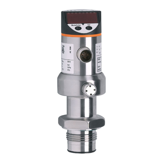
7 Operating and display elements 3 4 5 6 Mode/Enter 1 to 8: Indicator LEDs - LED 1 to LED 6 = system pressure in unit of measurement as indicated on the label� LEDs 5 to 6 not used for units with 3 adjustable units of measurement� - LED 7 not used�... -
Page 13: Menu
8 Menu 8.1 Menu structure... -
Page 14: 8�2 Menu Explanation
8.2 Menu explanation SP1/rP1 Maximum / minimum value for system pressure, at which output 1 changes its switching status� Output function for OUT1: • Switching signal for the limit values: hysteresis function [H ��] or window function [F ��], normally open [� no] or normally closed [� nc] each� •... -
Page 15: Parameter Setting
9 Parameter setting During the parameter setting process the unit remains in the operating mode� It continues its monitoring function with the existing parameters until parameter set- ting has been terminated� 9.1 Parameter setting general Each parameter setting requires 3 steps: Selecting parameter ►... - Page 16 ► Press [Set] and keep it pressed until the valid code no� is displayed� ► Press [Mode/Enter] briefly� Delivery by ifm electronic: no access restriction� • Locking / unlocking The unit can be locked electronically to prevent unintentional wrong settings�...
-
Page 17: 9�2 Configuring The Display (Optional)
9.2 Configuring the display (optional) ► Select [Uni] and set the unit of measurement: - [bAr], [mbAr], - [MPA], [kPA], - [PSI], - InHO] (only PI2996 and PI2997), - [mWS] (only PI2996 and PI2997)� ► Select [SELd] and set the display mode: - [P]: Pressure in the unit set in Uni�... -
Page 18: 9�3�2 Setting The Switching Limits
9.3.2 Setting the switching limits ► Select [SP1] and set the value at which OUT1 switches� ► Select [rP1] and set the value at which OUT1 switches back� rP1 is always lower than SP1� The unit only accepts values which are lower than SP1�... -
Page 19: 9�4 User Settings (Optional)
9.4 User settings (optional) 9.4.1 Zero-point calibration ► Select [COF] and set a value between -5% and 5% of the final value of the measuring range� The internal measured value “0” is shifted by this amount� As an alternative: Automatic adaptation offset (setting range 0 bar ±5%); e�g� in the event of a deviation of the mounting location of the sensor and the zero point level for level measurement�... -
Page 20: 9�5 Service Functions
9.5 Service functions 9.5.1 Reading the min./max. values for the system pressure ► Select [HI] or [LO], press [Set] briefly� [HI] = maximum value, [LO] = minimum value� Delete memory: ► Select [HI] or [LO]� ► Press [SET] until [----] is displayed� ►... -
Page 21: 10�3 Cleaning Of The Filter Cover
10.3 Cleaning of the filter cover If viscous and residues producing media clog the filter cover of the sen- sor (and thus reduce the measuring accuracy slightly), you can clean it� ► Unscrew the filter cover (B) (use a pair of pliers with plastic-covered jaws for this)�... -
Page 22: Scale Drawing
11 Scale drawing Dimensions are in millimeters 1: display 2: LED’s 3: programming button 12 Technical data Operating voltage [V] ������������������������������������������������������������������������������������������� 18���32 DC Current consumption [mA] ��������������������������������������������������������������������������������������������� < 50 Current rating [mA] ��������������������������������������������������������������������������������������������������������� 250 Short-circuit / reverse polarity / overload protection, integrated watchdog Voltage drop [V] ����������������������������������������������������������������������������������������������������������������<... - Page 23 Accuracy / deviation (in % of the span) - Characteristics deviation (linearity� incl� hysteresis and repeatability) ����������������������������������������������������������������������������������������������������������< ± 0�2 - Linearity ������������������������������������������������������������������������������������������������������������������< ± 0�15 - Hysteresis ���������������������������������������������������������������������������������������������������������������< ± 0�15 - Repeatability (with temperature fluctuations < 10 K) ������������������������������������������������< ± 0�1 - Long-term stability (in % of the span per year)���������������������������������������������������������<...
-
Page 24: 12�1 Setting Ranges
12.1 Setting ranges ΔP -0�96 25�00 -1�00 24�96 -1�00 18�74 5�24 25�00 0�02 -13�8 362�7 -14�4 362�1 -14�4 271�8 76�2 362�7 0�3 MPa -0�096 2�500 -0�100 2�496 -0�100 1�874 0�524 2�500 0�002 -0�98 10�00 -1�00 9�98 -1�00 7�50 1�50 10�00 0�01 -14�2 145�0... -
Page 25: Factory Setting
13 Factory setting Factory setting User setting 25% VMR* 23% VMR* ASP / tASP 0% VMR* AEP / tAEP 100% VMR* COF / tCOF bAr / mbAr SELd * = the indicated percentage of the final value of the measuring range (VMR) of the corresponding sensor in bar / mbar is set�...
Need help?
Do you have a question about the efector500 PI299 Series and is the answer not in the manual?
Questions and answers