Argo AE3MI70AH Technical & Service Manual
Dc inverter multi-system air conditioner
Hide thumbs
Also See for AE3MI70AH:
- Technical & service manual (45 pages) ,
- Installation instructions manual (24 pages)
Table of Contents
Advertisement
Quick Links
TECHNICAL & SERVICE MANUAL
OUTDOOR UNIT: AE2MI56AH
DC INVERTER MULTI-SYSTEM AIR CONDITIONER
2-room multi Outdoor unit
AE2MI56AH
3-room multi Outdoor unit
AE3MI70AH
AE3MI70AH
Capacity
Outdoor Model No.
5.6 kW
AE2MI56AH
6.8 kW
AE3MI70AH
Destination: General area (50Hz)
Product Code No.
< Combined Indoor Units >
Wall mounted type
AWMI28AHL
AWMI36AHL
AWMI50AHL
NOTE
1. How these units may be combined is given in
the Unit Combination Tables in the Appendix.
2. Be sure to operate the air conditioning
system only when 2 or more indoor units
have been installed. If operated with only a
single unit installed, the returning fluid to the
compressor may cause a malfunction.
IMPORTANT
These air conditioners employ
new refrigerant R410A.
Pay special attention when servicing
the unit.
NOV.2003
Europe (50Hz)
Australia (50Hz)
General area (60Hz)
Advertisement
Table of Contents

Related Manuals for Argo AE3MI70AH


Summary of Contents for Argo AE3MI70AH
- Page 1 TECHNICAL & SERVICE MANUAL NOV.2003 OUTDOOR UNIT: AE2MI56AH Destination: General area (50Hz) AE3MI70AH Europe (50Hz) Australia (50Hz) General area (60Hz) DC INVERTER MULTI-SYSTEM AIR CONDITIONER Capacity Outdoor Model No. Product Code No. 5.6 kW AE2MI56AH 6.8 kW AE3MI70AH < Combined Indoor Units >...
- Page 2 Important! When Transporting Be careful when picking up and moving the indoor and Please Read Before Starting outdoor units. Get a partner to help, and bend your knees when lifting to reduce strain on your back. Sharp This air conditioning system meets strict safety and edges or thin aluminum fins on the air conditioner can operating standards.
-
Page 3: Table Of Contents
Table of Contents Page 1. OPERATING RANGE ..........................1 2. SPECIFICATIONS 2-1. Unit Specifications .......................... 2 2-2. Major Component Specifications....................4 2-3. Other Component Specifications....................6 3. DIMENSIONAL DATA..........................7 4. REFRIGERANT FLOW DIAGRAM ......................9 5. PERFORMANCE DATA 5-1. Performance Charts (2-room multi) ....................11 5-2. -
Page 4: Operating Range
1. OPERATING RANGE Temperature Indoor Air Intake Temp. Outdoor Air Intake Temp. Maximum 32°C D.B. / 23°C W.B. 43°C D.B. Cooling Minimum 19°C D.B. / 14°C W.B. 19°C D.B. Maximum 27°C D.B. 24°C D.B. / 18°C W.B. Heating Minimum 16°C D.B. —... -
Page 5: Specifications
2. SPECIFICATIONS 2-1. Unit Specifications Outdoor Unit AE2MI56AH Type 2-room multi outdoor unit Number of connectable indoor units Maximum capacity of connected indoor units kW Maximum capacity of operating indoor units Power Source 220–240V ~ 50Hz 220V ~ 60Hz Voltage rating 230V 220V Performance... - Page 6 Outdoor Unit AE3MI70AH Type 3-room multi outdoor unit Number of connectable indoor units Maximum capacity of connected indoor units kW 11.4 Maximum capacity of operating indoor units 11.4 Power Source 220–240V ~ 50Hz 220V ~ 60Hz Voltage rating 230V 220V...
-
Page 7: Major Component Specifications
2-2. Major Component Specifications 2-2-1. Outdoor Unit Outdoor Unit AE2MI56AH Control PCB / HIC PCB / Filter PCB POW-CM5A1-C-T / CR-HIC30A2-C-T / POW-CM5B1-C-T Compressor Type DC Twin Rotary (Hermetic) Compressor model C-7RVN153H0W 80851080 Compressor oil … Amount FVC68S … 650 Ω... - Page 8 Outdoor Unit AE3MI70AH Control PCB / HIC PCB / Filler PCB POW-CM5A1-C-T / CR-HIC30A2-C-T / POW-CM5B1-C-T Compressor Type DC Twin Rotary (Hermetic) Compressor model C-7RVN153H0W 80851080 Compressor oil … Amount FVC68S … 650 Ω Coil resistance (Ambient temp. 25°C) R – S: 0.788 Ω...
-
Page 9: Other Component Specifications
AE2MI56AH AE3MI70AH... -
Page 10: Dimensional Data
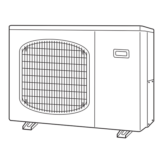
3. DIMENSIONAL DATA Outdoor Unit AE2MI56AH AIR INTAKE Drain hole AIR INTAKE AIR DISCHARGE AIR INTAKE Narrow tube service valve ø6.35 (1/4") Wide tube service valve ø9.52 (3/8") Unit: mm... - Page 11 Outdoor Unit AE3MI70AH AIR INTAKE Drain hole AIR INTAKE AIR DISCHARGE AIR INTAKE Narrow tube service valve ø6.35 (1/4") Wide tube service valve ø9.52 (3/8") unit: mm...
-
Page 12: Refrigerant Flow Diagram
4. REFRIGERANT FLOW DIAGRAM Outdoor Unit AEMI56AH 2-Room Multi Refrigerant Tubing System Diagram Unit: mm Service valve on wide tube When cooling side When heating When defrosting Four-way valve Muffler Solenoid valve for hot gas bypass Muffler Outdoor Indoor unit heat Main exchanger... - Page 13 Outdoor Unit AE3MI70AH 3-Room Multi Refrigerant Tubing System Diagram Unit: mm When cooling Service valve on When heating wide tube side When defrosting Four-way valve Muffler Solenoid valve for hot gas bypass Muffler Outdoor Indoor unit heat Main exchanger accumulator...
-
Page 14: Performance Data
5. PERFORMANCE DATA 5-1. Performance Charts (2-room multi) Outdoor Unit AE2MI56AH Indoor Unit AWMI28HLA X 1 • Heating Characteristics • Cooling Characteristics (1) Low pressure performance chart (1) High pressure performance chart (RH: 46%, Indoor fan speed: High fan) (RH: 85%, Indoor fan speed: High fan) (50/60Hz, 220V) (50/60Hz, 220V) Lo fan... - Page 15 Outdoor Unit AE2MI56AH Indoor Unit AWMI38HLA X 1 • Heating Characteristics • Cooling Characteristics (1) Low pressure performance chart (1) High pressure performance chart (RH: 46%, Indoor fan speed: High fan) (RH: 85%, Indoor fan speed: High fan) (50/60Hz, 220V) (50/60Hz, 220V) Lo fan Hi fan...
- Page 16 Outdoor Unit AE2MI56AH Indoor Unit AWMI50AHL X 1 • Heating Characteristics • Cooling Characteristics (1) Low pressure performance chart (1) High pressure performance chart (RH: 46%, Indoor fan speed: High fan) (RH: 85%, Indoor fan speed: High fan) (50/60Hz, 220V) (50/60Hz, 220V) Lo fan Hi fan...
-
Page 17: Performance Charts (3-Room Multi)
5-2. Performance Charts (3-room multi) Outdoor Unit AE3MI70AH AWMI28AHL × × 1 Indoor Unit • Cooling Characteristics • Heating Characteristics (1) Low pressure performance chart (1) High pressure performance chart (RH: 46%, Indoor fan speed: High fan) (RH: 85%, Indoor fan speed: High fan) - Page 18 Outdoor Unit AE3MI70AH AWMI38AHL × × 1 Indoor Unit • Heating Characteristics • Cooling Characteristics (1) Low pressure performance chart (1) High pressure performance chart (RH: 46%, Indoor fan speed: High fan) (RH: 85%, Indoor fan speed: High fan) (50/60Hz, 220V)
- Page 19 Outdoor Unit AE3MI70AH AWMI50AHL × × 1 Indoor Unit yp ( • Heating Characteristics • Cooling Characteristics (1) Low pressure performance chart (1) High pressure performance chart (RH: 46%, Indoor fan speed: High fan) (RH: 85%, Indoor fan speed: High fan)
-
Page 20: Electrical Data
6. ELECTRICAL DATA 6-1. Electric Wiring Diagrams Outdoor Unit AE2MI56AH Electric Wiring Diagram for 2-room multi outdoor unit (AWMI28AHL) Before replacing PCBs, turn off the power and check that all CAUTION lamps on the PCB are off before starting work. Electric shock will occur if work is performed while the lamps are lit. - Page 21 Outdoor Unit AE3MI70AH Electric Wiring Diagram for 3-room multi outdoor unit Before replacing PCBs, turn off the power and check that all CAUTION lamps on the PCB are off before starting work. Electric shock will occur if work is performed while the lamps are lit.
-
Page 22: Installation Instructions
7. INSTALLATION INSTRUCTIONS Installation Site Selection 7-1. Indoor Unit To prevent abnormal heat generation and the WARNING possibility of fire, do not place obstacles, enclosures and grilles in front of or surrounding the air conditioner in a way that may block air flow. AVOID: direct sunlight. - Page 23 Indoor unit φ6.35 (28-38 types) φ9.52 φ9.52 φ6.35 (50 type) φ9.52 φ9.52 (Less than 17 m) Fig. 2b (2) Connecting indoor unit types (28-38-50) for AE3MI70AH Outdoor unit Indoor unit φ6.35 (28-38 types) φ9.52 φ6.35 φ9.52 (28 38 types) φ9.52 φ9.52 φ6.35...
-
Page 24: Outdoor Unit
7-2. Outdoor Unit Exhaust fan AVOID: Hot air Heat source heat sources, exhaust fans, etc. (Fig. 3) damp, humid or uneven locations. Outdoor unit choose a place as cool as possible. choose a place that is well ventilated. Fig. 3 allow enough room around the unit for air intake/ exhaust and possible maintenance. -
Page 25: Diagram Of Outdoor Unit Installation
7-3. Diagram of Outdoor Unit Installation Never install only a single indoor unit. Be sure to connect indoor and outdoor units only in combinations that are listed in the catalog or in the combination table that was provided with the indoor unit. -
Page 26: Recommended Wire Length And Diameter
A – C. 7-5. Wiring System Diagram 3 indoor units with AE3MI70AH 2 indoor units with AE2MI56AH Outdoor Unit Indoor Unit Terminal plate (12P) -
Page 27: Functions
8. FUNCTIONS 8-1. Defrost Detection and End 8-1-1. Non-stop defrosting Defrost sequence 4-way valve ON Defrost detection occurs in either of the following cases: • The temperature of the heat exchanger remains at or below the L1 line for 35 minutes after the start of HEAT operation. •... -
Page 28: Current Control
8-2. Current Control 8-3. Low Start Current The operating current may rise as a result of causes Operation starts at 10 Hz, and the start current is less than including increasing heating or cooling loads or the normal operating current. This prevents the flickering of decreases in power voltage. -
Page 29: Control At Heat Start-Up
8-5-2. HEAT operation (1) The fan speed is changed as shown in the figure below, based on the outdoor air temperature and the operating frequency. 5°C or below Above 5°C Outdoor air 5°C Above 35 Hz Fan H Fan H 35 Hz Frequency Fan H Fan L... -
Page 30: Troubleshooting
9. TROUBLESHOOTING Both the indoor unit and outdoor unit include electronic control circuits. Be sure to pay attention to the following before inspecting or repairing the outdoor-side electronic circuits. High-capacity electrolytic capacitors are used inside the outdoor unit controller (inverter). They retain an electrical charge (charging voltage DC 311 V) even after the power is turned OFF, and some time is required for the charge to dissipate. -
Page 31: Outdoor Unit Trouble Diagnostics
9-2. Outdoor Unit Trouble Diagnostics If a protective device has activated or there is a sensor failure in the outdoor unit, the 6 error monitor lamps on the outdoor control circuit board will indicate the nature of the trouble. : ON : OFF E R R E R R... -
Page 32: Checking The Outdoor System
9-3. Checking the Outdoor System 9-3-1. Checking the outdoor unit Control Check items (unit operation) • Apply 220 V AC between terminals 1 and 2 on the • The LED (red) on the control circuit board must outdoor unit 3P terminal block. illuminate. -
Page 33: Unit Problems And Inspection Points
9-4. Unit Problems and Inspection Points Indoor unit Outdoor unit Others Problems Note Inspection points Self-Diagnostics check 1 Indoor controller (control unit) 2 Indoor fan motor 3 Room temperature sensor 4 Heat exchanger temperature sensor 5 Inter-unit cable 6 Switch circuit board 7 Outdoor control circuit board 8 Diode module... - Page 34 9-4-1. Outdoor control circuit board Refer to 9-3-1. Checking the outdoor unit. NOTE: Do not remove or insert the outdoor control circuit board connector when power is being supplied to it. (The controller will be damaged.) 9-4-2. HIC HIC measurement points –...
- Page 35 9-4-9. Electric expansion valve When replacing the electric expansion valve and coil, be sure to attach the connectors in the correct positions. Labels are applied to the valve body and coil, corresponding to the connector colors, to identify them. Use a tester to measure the voltage (12 V). When the power is turned ON, the needle will move from MMV (white) →...
-
Page 36: Explanation Of Functions
9-5. Explanation of Functions e i l t i s operation c i t e i l c i t button on the remote e l l controller is pressed. operational mode, refer to the HEAT, SENSOR DRY, or COOL item. operation u l l button on the remote... - Page 37 When defrost operation Non-stop defrost begins, frost has formed on the outdoor unit (when the ambient air Non-stop defrost (Refer to Fig. 1 below.) temperature is low). n i l n i l ) . t o l l . t i v i t 1 below.
- Page 38 The ON/OFF operation button on the remote minutes even after the breaker is turned ON. controller is pressed. . s t ) . t α z i l f o β 2 below.) v i t z i l t I ( l l i c i t .
- Page 39 (1/f fluctuation fan) operation button on the remote minutes even after the breaker is turned ON. controller is pressed. . s t ) . t α z i l β v i t . s t z i l v i t y f i “Low”...
-
Page 40: Refrigerant R410A: Special Precautions When Servicing Unit
10. REFRIGERANT R410A: SPECIAL PRECAUTIONS WHEN SERVICING UNIT 10-1. Characteristics of New Refrigerant R410A 10-1-1. What is New Refrigerant R410A? R410A is a new refrigerant that contains two types of pseudo-non-azeotropic refrigerant mixture. Its refrigeration capacity and energy efficiency are about the same level as the conventional refrigerant, R22. 10-1-2. - Page 41 Tubing precautions Refrigerant R410A is more easily affected by dust or moisture compared with R22, thus be sure to temporarily cover the ends of the tubing with caps or tape prior to installation. Never use 0.7mm-thick copper tubing or tubing which is less than 0.8mm in thickness, since air conditioners with R410A are subject to higher pressure than those using R22 and R407C.
-
Page 42: Tools Specifically For R410A
10-3. Tools Specifically for R410A For servicing, use the following tools for R410A Tool Distinction Tool Name Gauge manifold Charging hose Gas leak detector Refrigerant cylinder Charging cylinder Refrigerant recovery unit Vacuum pump with anti-reverse flow (*1) Tools specifically for R410A (Solenoid valve-installed type, which prevents oil from flowing back into the unit when the power is off, is recommended.) Vacuum pump (*2) …... -
Page 43: In Case Of Compressor Malfunction
10-5. In Case of Compressor Malfunction Should the compressor malfunction, be sure to make the switch to a replacement CAUTION compressor as quickly as possible. Use only the tools indicated exclusively for R410A. See “10-3. Tools Specifically for R410A.” 10-5-1. Procedure for replacing compressor (1) Recovering refrigerant Any remaining refrigerant inside the unit should not be released to the atmosphere, but recovered using the... - Page 44 (5) Recharging Configuration and characteristics of cylinders Valve Be sure to charge the specified amount of refrigerant in liquid state using the service port of the wide tube service valve. The proper amount is listed on the unit's nameplate. When the entire amount cannot be charged all at once, charge gradually while operating the unit in Cooling Operation.
-
Page 45: In Case Refrigerant Is Leaking
10-6. In Case Refrigerant is Leaking Never attempt to charge additional refrigerant when refrigerant has been leaking CAUTION from the unit. Follow the procedure described below to locate points of leaks and carry out repairs, then recharge the refrigerant. (1) Detecting Leaks Use the detector for R410A to locate refrigerant leak (1) Detect leaks points. - Page 46 (6) Recharging Configuration and characteristics of cylinders Valve Be sure to charge the specified amount of refrigerant in liquid state using the service port of the wide tube service valve. The proper amount is listed on the unit's nameplate. When the entire amount cannot be charged all at once, charge gradually while operating the unit in Cooling Operation.
-
Page 47: Charging Additional Refrigerant
10-7. Charging Additional Refrigerant 10-7-1. When Tubes are Extended Observe the proper amount of refrigerant as stated in this service manual or the installation manual that came with the indoor unit. Charge additional refrigerant in liquid state only. Never charge additional refrigerant if refrigerant is leaking from the unit. Follow CAUTION instructions given in “10-6. -
Page 48: Appendix
APPENDIX UNIT COMBINATION TABLES NOTE Be sure to operate the air conditioning system only when 2 or more indoor units have been installed. If operated with only a single unit installed, the returning fluid to the compressor may cause a malfunction. - Page 49 2-Room Outdoor Unit Combination Table Outdoor Unit AE2MI56AH NOTE 2.8: AWMI28AH 3.6: AWMI38AH Single-room operation 5.0: AWMI50AH Single-room operation Indoor Unit Capacity (kW) Indoor Unit Indoor unit Combination Conbination Room A Room B Room C Total Performance Power Input (W) Current (A) Min.
- Page 50 3-Room Outdoor Unit Combination Table Outdoor Unit AE3MI70AH NOTE 2.8: AWMI28AHL 3.6: AWMI38AHL Single-room operation 5.0: AWMI50AHL Single-room operation Indoor Unit Capacity (kW) Indoor Unit Indoor unit Combination Conbination Room A Room B Room C Total Performance Power Input (W) Current (A) Min.
- Page 51 Outdoor Unit AE4MI91AH NOTE 2.8: AWMI28AHL 3.6: AWMI38AHL 3-room operation Three-room operatio 5.0: AWMI50AHL Indoor Unit Capacity (kW) Indoor unit Indoor Unit Conbination Combination Room A Room B Room C Total Performance Power Input (W) Current (A) Min. - Max. Min.
- Page 52 ARGOCLIMA SPA. GALLARATE-ITALY...
Need help?
Do you have a question about the AE3MI70AH and is the answer not in the manual?
Questions and answers
Ik heb een printplaat dat stuk is , waar zou ik deze kunnen bestellen ?