
Subscribe to Our Youtube Channel
Related Manuals for Vision Tech Shop MVS1 Series


Summary of Contents for Vision Tech Shop MVS1 Series
- Page 1 MVS1 Operation / Technical Manual Contents subject to change without notice Version 1.0...
-
Page 2: Table Of Contents
TABLE OF CONTENTS 1. INTRODUCTION and INSTALLATION ..................2 General and Safety Information ........................2 Specifications ..............................2 Contents ................................3 Installation ................................3 2. OVERVIEW OF CONTROLS AND FUNCTIONS ................. 4 Indicator Display Character Definitions ......................4 Indicator Display..............................5 Function Keys .............................. -
Page 3: Introduction And Installation
Electronic scales are precision instruments. Do not operate near cell phones, radios, computers or other electronic devices that emit radio frequencies that may cause unstable readings. Avoid using in heavy vibration or heavy airflow conditions. Specifications Model MVS1 Series 77lb (35kg) 165lb (75kg) 440lb (200kg) Max Capacity 0.05lb (0.02kg) -
Page 4: Contents
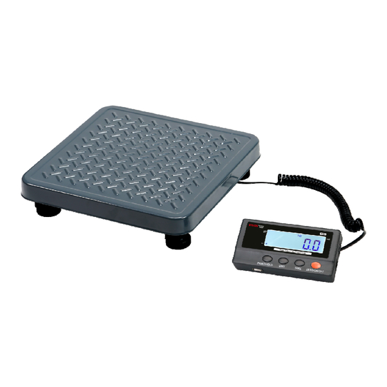
Contents Indicator & Scale Platform Outer Hexagonal Wrench DC9V 600mA UL Adapter Owner’s Manual Installation 1. Remove the scale from the packaging and place it on a work table with the feet facing up. Remove the shipping protection screw. See below pictures. 2. -
Page 5: Overview Of Controls And Functions
2. OVERVIEW OF CONTROLS AND FUNCTIONS Indicator Display Character Definitions... -
Page 6: Indicator Display
Indicator Display ZERO- Scale is zeroed and gross weight is 0, tare is 0. NET - Display reading is net weight; tare is not 0. lb, kg, oz - Unit of measure. HOLD - Scale is in dynamic weighing mode. - Hold flashes - actual fluctuating weight is displayed. -
Page 7: Operations
3. OPERATIONS Normal Weighing Mode 1. Power on the scale by pressing the ZERO/ON/OFF key. 2. When the display stabilizes, but it doesn’t show zero, press ZERO/ON/OFF to set a new zero point. 3. Place objects on the scale platform and read the weight on the indicator. Note: Objects should be placed at the center of the platform. -
Page 8: Calibration
4. Calibration Note: (1) Before calibrating the scale, you should prepare standard weights (more than 10% of FS weight) for calibration. (2) In the following steps, pressing ZERO/ON/OFF will exit calibration. 1. Move all weight from the scale. Under normal weighing mode, press and hold TARE and ZERO/ON/OFF keys for more than 4s to enter calibration mode. -
Page 9: View Adc Code Or Power Voltage
5. View ADC Code or Power Voltage 1. In normal weighing mode, press and hold HOLD/PRINT and ZERO/ON/OFF keys until “ ” is shown, which means the indicator is working under display inner code mode. In this mode, you can examine the stability of the weighing system, the increment value of ADC code corresponding to the loaded weight, and/or power voltage to PCB. -
Page 10: Configuration Parameters Setup
6. Configuration Parameters Setup 1. When the scale is off, press and hold ZERO/ON/OFF and PRINT/HOLD keys until ‘C0NF’ is shown, which indicates that the scale is in Configuration parameter setup mode. 2. During setup mode, press the UNIT key to change the flashed digits, and use the HOLD/PRINT key to shift the flashed position. - Page 11 Para- 77lb 165lb 400lb Default Setting meter setting setting setting Zero range for ZERO/ON/OFF button: 0 –power-on zero -point ±1%FS; 1 - power-on zero –point ±2%FS; 2 - power-on zero –point ±3%FS; 3 - power-on zero –point ±4%FS; 4 - power-on zero –point ±5%FS; 8 8 8 8 5 - power-on zero –point ±10%FS;...
- Page 12 Table1: use Kg as calibration unit: Display division value in different weight unit that can be used Calibration division value lb:oz 0.0001kg 0.0001kg 0.0002lb Not available 0.001kg 0.001kg 0.002lb Not available 0.01kg 0.01kg 0.02lb 0.5oz 0.1kg 0.1kg 0.2lb 5 oz Not available 10kg 10kg...
- Page 13 4. More Information for Configuration Parameters: 4.1 The division (d) of scale is determined by C3,C4 and C5 : If C3=3 (interval is 5), C4=2(decimal point is x.xx), C5=1(unit is lb), Then C3xC4xC5=5x0.01xlb=0.05lb, So, d=0.05lb 4.2 The capacity is determined by C1 and d : If C1=3000, d=0.05lb, then C1xd=3000x0.05lb=150.00lb, So, the capacity (FS) is 150.00lb 4.3 Operation on C16 :...
-
Page 14: User Parameters Setup
7. User Parameters Setup 1. In normal weighing mode, press UNIT and ZERO/ON/OFF until “ ” is shown to enter in USer the mode. 2. In this mode, press the UNIT key to change the flashed digits, press the HOLD/PRINT key to shift the flashed position. - Page 15 4. More Information for User Parameters Setting: U5 to set serial communication output format: (1). U5=0: No serial communication function. It will not transmit or receive any data even if the scale is installed with serial communication hardware. Serial communication function can be only activated when the scale is in normal weighing mode.
- Page 16 “lb” and one for a space (<sp>) after lb. Units of measure abbreviations are always lower case. (1). If the weight is overcapacity, the scale will return ten ‘^’ characters (the field of minus sign, decimal point, weight data is filled by ‘^’). (2).
- Page 17 scale status. (4). Command: T<CR> (54h 0dh) Response: <LF> H1H2H3<CR><ETX> TARE function is activated, and then returns scale status, similar to pressing the TARE key. If TARE function cannot be activated, it will return to current scale status. (5). Command: U<CR> (55h 0dh) Response: <LF>u1u2<CR><LF>...
-
Page 18: Symbol Definitions
Byte 1 (H1) Byte 2 (H2) Byte 3 (H3) 0=not AD over 0=not Zero Over 0= gross weight 1=AD over 1=Zero Over 1= net weight 0= eeprom OK 0=not Zero down 0=not AD down 1= eeprom error 1= Zero down 1=AD down always 1 always 1... -
Page 19: Trouble Shooting
9. 9. 9. 9. Trouble shooting Trouble shooting Trouble shooting: : : : Trouble shooting SYMPTOM PROBABLE CAUSE REMEDY 1. Re-plug the AC adapter or rotate the 1. AC adapter is not securely connected plug to securely connect to the scale Does not turn on. - Page 20 www.VisionTechShop.com 100 Temple Ave. Hackensack, NJ 07601 Tel: + 1-201-679-7793...
Need help?
Do you have a question about the MVS1 Series and is the answer not in the manual?
Questions and answers