
Subscribe to Our Youtube Channel
Related Manuals for Woods RBS54


Summary of Contents for Woods RBS54
- Page 1 REAR BLADE & LANDSCAPE RAKE RBS54 RBS60 RBS72 LRS52 LRS60 LRS72 RBS60P RBS72P RBS84P LRS72P LRS84P LRS96P CD8122 MAN1047_2024-07.indd 1 MAN1047_2024-07.indd 1 7/3/24 9:20 AM 7/3/24 9:20 AM...
-
Page 2: Introduction
TO THE OWNER: Read this manual before operating your Woods equipment. The information presented will prepare you to do a better and safer job. Keep this manual handy for ready reference. Require all operators to read this manual carefully and become acquainted with all adjustment and operating procedures before attempting to operate. -
Page 3: Table Of Contents
TABLE OF CONTENTS INTRODUCTION..........2 SPECIFICATIONS . -
Page 4: Specifications
SPECIFICATIONS RBS54 RBS60P LRS52 LRS72P Models RBS60 RBS72P LRS60 LRS84P RBS72 RBS84P LRS72 LRS96P Unit Weight (Pounds) 134, 142, 156 268, 288, 308 156, 168, 186 264, 288, 311 Horse Power 30 HP Max 20 - 45 HP 30 HP Max... -
Page 5: Safety 5
SAFETY RULES ATTENTION! BECOME ALERT! YOUR SAFETY IS INVOLVED! ■ Power unit must be equipped with ROPS or ROPS cab and seat belt. Keep seat belt secure- Safety is a primary concern in the design and man- ly fastened. Falling off power unit can result in ufacture of our products. -
Page 6: Maintenance
SAFETY RULES ATTENTION! BECOME ALERT! YOUR SAFETY IS INVOLVED! MAINTENANCE ■ Do not operate or transport on steep slopes. ■ Do not stop, start, or change directions sudden- ■ Before dismounting power unit or perform- ly on slopes. ing any service or maintenance, follow these steps: disengage power to equipment, lower ■... -
Page 7: Safety & Instructional Decals
SAFETY & INSTRUCTIONAL DECALS ATTENTION! BECOME ALERT! YOUR SAFETY IS INVOLVED! Replace Immediately If Damaged! SERIAL NUMBER PLATE LOCATION SERIAL NUMBER PLATE LOCATION Safety 7 MAN1047 ( 07/02/2024 ) MAN1047_2024-07.indd 7 MAN1047_2024-07.indd 7 7/3/24 9:20 AM 7/3/24 9:20 AM... - Page 8 Replacement safety decals can be ordered free from your Woods dealer. To locate your near- est dealer, check the Dealer Locator at www.WoodsEquipment.com, or in the United States and Canada call 1-800-319-6637.
-
Page 9: Operation 9
OPERATION The operator is responsible for the safe operation of this equipment. Operators must be instructed in and be capable of the safe operation of the equipment, its attachments and all controls. Do not allow anyone to operate this equipment without proper instructions. This equipment is designed for a wide range of appli- cations. -
Page 10: Operating Techniques
When using the rake tool, you may need to adjust the tail wheels after adjusting pitch to maintain the desired working depth. Position 3-point lift arm sway blocks or tighten sway chains to eliminate side sway. Install side braces if necessary. -
Page 11: Parking Stand Placement (Optional)
Backfilling PARKING STAND PLACEMENT (OPTIONAL) Reverse blade for backfilling ditches or trenches (see Reversing). Assembly The rake may also be used in light backfilling 1. Assemble parking stand holder (1) toward center of applications. frame assembly using 3/8 hex head cap screw (3), 3/8 flat washers (4) and secure with 3/8 hex nut (5). -
Page 12: Tail Wheel Adjustment (Optional)
TAIL WHEEL ADJUSTMENT (OPTIONAL) TAIL WHEEL ADJUSTMENT (OPTIONAL) (BASIC SERIES BLADE ONLY) (PREMIUM SERIES BLADE ONLY) CD8139 CD8140 1. Yoke & wheel assembly 1. Yoke & wheel assembly 2. Tail wheel arm 2. Tail wheel arm 3. 1/2" Thick spacer 3. -
Page 13: Pre-Operation Checklist
PRE-OPERATION CHECKLIST (OWNER’S RESPONSIBILITY) Review and follow all safety rules and safety Make sure tractor ROPS or ROPS cab and seat decal instructions on pages 5 through 8. belt are in good condition. Keep foldable ROPS systems in “locked up” position at all times. Keep Check that all safety decals are installed and in seat belt securely fastened during operation. -
Page 14: 14 Maintenance
MAINTENANCE The information in this section is written for operators REPLACING BLADE CUTTING EDGE who possess basic mechanical skills. If you need help, your dealer has trained service technicians available. Remove Cutting Edge For your protection, read and follow all safety informa- tion in this manual. -
Page 15: Rake Tine Replacement
■ Inspect machine and replace worn or damaged parts. ■ Sand down scratches and the edges of areas of missing paint and coat with Woods spray paint of matching color (purchase from your Woods dealer). 1. Rake tine ■... -
Page 16: 16 Assembly
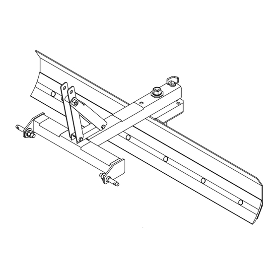
BLADE AND RAKE ASSEMBLY Assembly of this Rear Blade/Landscape Rake is the re- Blade and Rake Assembly (Basic) sponsibility of the Woods dealer. It should be delivered to the owner completely assembled, lubricated and ad- 1. Assemble frame assembly onto threaded stud on justed for normal cutting conditions. - Page 17 Blade Assembly (Premium) Install hitch pin (16) thru hole in frame and into de- sired hole in pivot assembly. 1. Remove clamp channel (4) from pivot assembly (3). 4. Assemble left and right mast plates (8 & 9) to frame Insert clamp channel into main channel on back of assembly (1) using 1/2 NC x 3-1/2 hex cap screws moldboard (2).
-
Page 18: Tail Wheel Installation (Optional) (Landscape Rake Only)
TAIL WHEEL INSTALLATION (OPTIONAL) (LANDSCAPE RAKE ONLY) 1. Remove landscape rake from tractor 3-point lift arms if attached. 2. Roll landscape rake over with tines pointing upward. 3. Place jack stands or suitable blocking device under tine beam to raise tine beam approximately 8 to 10 inches. -
Page 19: Quick Hitch Bushing Kit (Optional)
QUICK HITCH BUSHING KIT (OPTIONAL) PARKING STAND (OPTIONAL) Assembly 1. Assemble parking stand holder (1) toward center of frame assembly using 3/8 NC hex cap screw (3), 3/8 flat washers (4) and secure with 3/8 NC hex nut (5). Do not allow parking stand holder to cover any portion of safety decal. -
Page 20: Category 0 / 1 Hitch Pin Kit (Optional)
CATEGORY 0 / 1 HITCH PIN KIT SKID SHOE KIT (OPTIONAL) (OPTIONAL) 1. Remove plow bolts from each end of cutting edge. 1. Remove existing hitch pins. 2. Attach skid shoe (1) to rear of moldboard with 5/8 NC x 2 plow bolt (2), 5/8 hardened flat washer (3) 2. - Page 21 SKID SHOE KIT (OPTIONAL) 1. Remove plow bolts from each end of cutting edge. 2. Attach right and left skid shoe brackets (3 & 4) to rear of moldboard with plow bolts (8), washers (9), and lock nuts (10) supplied in kit. Top of skid shoe brackets should angle slightly toward edge of blade.
-
Page 22: 22 Dealer Checklists
DEALER CHECKLISTS PRE-DELIVERY CHECKLIST DELIVERY CHECKLIST (DEALER’S RESPONSIBILITY) (DEALER’S RESPONSIBILITY) Show customer how to make adjustments. Inspect the equipment thoroughly after assembly to be certain it is set up properly before delivering it to the Instruct customer how to lubricate and explain customer. -
Page 23: Parts Index
PARTS INDEX REAR BLADE & LANDSCAPE RAKE RBS54, RBS60, RBS72 LRS52, LRS60, LRS72 RBS60P, RBS72P, RBS84P LRS72P, LRS84P, LRS96P RBS & LRS BASIC ASSEMBLY ......24 - 25 RBS ASSEMBLY . - Page 24 RBS54, RBS60 & RBS72 ASSEMBLY LRS52, LRS60 & LRS72 ASSEMBLY CD8132 24 Parts MAN1047 ( 07/02/2024 ) MAN1047_2024-07.indd 24 MAN1047_2024-07.indd 24 7/3/24 9:20 AM 7/3/24 9:20 AM...
- Page 25 RBS54, RBS60 & RBS72 ASSEMBLY LRS52, LRS60 & LRS72 ASSEMBLY PART DESCRIPTION PART DESCRIPTION 103741154RP RBS54 Moldboard 11900 * A/R 1/2 NC Flange hex lock nut 103741160RP RBS60 Moldboard 25265 A/R 5/8 NC x 1-1/2 Plow bolt 103741172RP RBS72 Moldboard...
- Page 26 1037504RP Right mast plate 1037524 1-1/4 NC Nylock hex nut, GR8 1037503RP Left mast plate 1037539 Decal, Model, Woods RBS60P 1004661RP Sleeve, .812 x 1.25 x 2.00 1037540 Decal, Model, Woods RBS72P Category 1 mounting pin 1037541 Decal, Model, Woods RBS84P...
- Page 27 25258 RBS72 Cutting edge -or- 1037524 1-1/4 NC Nylock hex nut, GR8 46440 RBS84 Cutting edge 1037539 Decal, Model, Woods RBS60P 1004661 Sleeve, .812 x 1.25 x 2.00 1037540 Decal, Model, Woods RBS72P Category 1 mounting pin 1037541 Decal, Model, Woods RBS84P...
- Page 28 30007 * 7/8 NF hex nut 103753796RP LRS96P Clamp channel 1037524 1-1/4 NC Nylock hex nut, GR8 10562 A/R LRS Rake tine 1037542 Decal, Model,Woods LRS72P 1037504RP Right mast plate 1037543 Decal, Model,Woods LRS84P 1037503RP Left mast plate 1037544 Decal, Model,Woods LRS96P 1004661RP Sleeve, .812 x 1.25 x 2.00...
- Page 29 103753784RP LRS84P Clamp channel -or- 1037524 1-1/4 NC Nylock hex nut, GR8 103753796RP LRS96P Clamp channel 1037542 Decal, Model,Woods LRS72P 10562 A/R LRS Rake tine 1037543 Decal, Model,Woods LRS84P 1004661RP Sleeve, .812 x 1.25 x 2.00 1037544 Decal, Model,Woods LRS96P Category 1 mounting pin NOTE: For safety decals, see pages 7 and 8.
- Page 30 RBS & LRS PARKING STAND (OPTIONAL) PART DESCRIPTION Parking stand kit 1037480 (For Basic) -or- Parking stand kit CD8136 1037450 (For Premium) Parking stand mounting 1037481 bracket (For Basic) -or- Parking stand mounting 1037451 bracket (For Premium) 1021062RP Parking stand 3/8 NC x 3-3/4 HHCS, GR5 13927 * (Basic)
- Page 31 LRS TAIL WHEEL (OPTIONAL) PART DESCRIPTION 1037437 Tail wheel kit, LRS 1037434RP Tail wheel arm 1037435RP Tail wheel clevis yoke 65129 Pipe, SCH 40 x .50, Spacer Wheel, 7.75 x 3.5 x .75 66965 (Includes bearings item 5) 65577 Flange bearing, .75 x 1.415 29368 Sleeve, .50 x .75 x 3.38 62043 *...
- Page 32 LRS TAIL WHEEL (PREMIUM) (OPTIONAL) PART DESCRIPTION 1037589RP Tail wheel kit, (Premium) 1037534RP Tail wheel arm 1008032RP Tail wheel clevis yoke 65129 Pipe, SCH 40 x .50, Spacer 65130 Pipe, SCH 40 x 1.00, Spacer Wheel, 10.0 x 3.25 x .75, 19754 Pneum (Includes bearings items 6 &...
- Page 33 18300 PREMIUM SKID SHOE KIT (OPTIONAL) PART DESCRIPTION 18300 Skid shoe kit (Premium) ----- Blade assembly 27586RP Skid & shaft assembly Bracket, skid shoe 1005328RP right (not shown) 1005329RP Bracket, skid shoe left CD5833B 52854 Sleeve, 1.28 x 1.66 x .75 27542 Pin, klik 7/16 x 2 7163 *...
-
Page 34: Appendix
BOLT TORQUE CHART Always tighten hardware to these values unless a different torque value or tightening procedure is listed for a specific application. Fasteners must always be replaced with the same grade as specified in the manual parts list. Always use the proper tool for tightening hardware: SAE for SAE hardware and Metric for metric hardware. Make sure fastener threads are clean and you start thread engagement properly. -
Page 35: Bolt Size Chart & Abbreviations
BOLT SIZE CHART NOTICE: Chart shows bolt thread sizes and corresponding head (wrench) sizes for standard SAE and metric bolts. SAE BOLT THREAD SIZES 5/16 10mm 12mm 14mm 16mm 18mm METRIC BOLT THREAD SIZES ABBREVIATIONS AG ....Agriculture HT . - Page 36 Woods logo are trademarks of Woods Equipment Company. All other ® trademarks, trade names, or service marks not owned by Woods Equipment Company that appear in this manual are the property of their respec tive companies or mark holders. Specifications subject to change without notice.
Need help?
Do you have a question about the RBS54 and is the answer not in the manual?
Questions and answers