Table of Contents
Advertisement
Advertisement
Table of Contents

Subscribe to Our Youtube Channel
Related Manuals for Woods HSS72


Summary of Contents for Woods HSS72
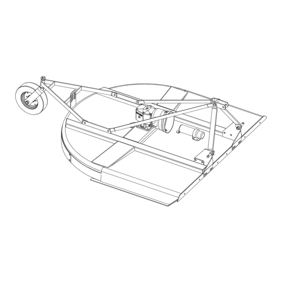
- Page 1 HERITAGE ROTARY CUTTER HSS60 HSS72 Tested. Proven. Unbeatable.
-
Page 2: Introduction
Operator’s Manual. If using the mail-in form, the dealer is to return the prepaid postage portion to Woods, give one copy to the customer, and retain one copy. Failure to register the product does not diminish customer’s warranty rights. -
Page 3: Table Of Contents
TABLE OF CONTENTS INTRODUCTION ..........2 SPECIFICATIONS. -
Page 4: Specifications
SPECIFICATIONS 3-Point Hitch ......HSS60 / HSS72; Category 1 Cutting Height ..........1" - 9"... -
Page 5: Safety Video Order Form
Safety Video Order Form BE SAFE! BE ALERT! BE ALIVE! BE TRAINED Before Operating Mowers! Safety Training Does Make a Difference. ASSOCIATION OF EQUIPMENT MANUFACTURERS Free Mower Safety Video Fill out and return the order form and we will send you a FREE VHS or DVD video outlining Industrial and Agricultural Mower Safety Practices . - Page 6 DVD Format - DVD01052 Safety Video Name: ________________________________________ Phone: __________________ Address: _____________________________________ _____________________________________ _____________________________________ Mower/Cutter Model: ______________________ Serial #: ________________________ Send to: ATTENTION: DEALER SERVICES WOODS EQUIPMENT COMPANY PO BOX 1000 OREGON IL 61061-1000 6 Safety Safety Video Order Form (Rev. 2/6/2006)
-
Page 7: Safety Rules
SAFETY RULES ATTENTION! BECOME ALERT! YOUR SAFETY IS INVOLVED! Make sure spring-activated locking pin or collar Safety is a primary concern in the design and slides freely and is seated firmly in tractor PTO manufacture of our products. Unfortunately, our spline groove. - Page 8 SAFETY RULES ATTENTION! BECOME ALERT! YOUR SAFETY IS INVOLVED! (Safety Rules continued from previous page) Leak down or failure of mechanical or hydraulic system can cause equipment to drop. Full chain, rubber, or steel band shielding, designed to reduce the possibility of thrown MAINTENANCE objects, must be installed when operating in popu- lated areas or other areas where thrown objects...
- Page 9 SAFETY RULES ATTENTION! BECOME ALERT! YOUR SAFETY IS INVOLVED! Disconnect cutter driveshaft and secure up off Leak down or failure of mechanical or hydraulic ground. Raise cutter with 3-point hitch. Place system can cause equipment to drop. blocks under cutter side skids. Lower cutter onto STORAGE blocks.
-
Page 10: Safety Decals
SAFETY & INSTRUCTIONAL DECALS ATTENTION! BECOME ALERT! YOUR SAFETY IS INVOLVED! Replace Immediately If Damaged! 1 - SERIAL NUMBER PLATE MODEL NO. SERIAL NO. Woods Equipment Company Oregon, Illinois, U.S.A. 6 - PN 20106 RED REFLECTOR 4.5" 8 - PN 1006682 DANGER... - Page 11 Replacement safety decals can be ordered free in gear. Make sure parking brake is engaged before going between from your Woods dealer. To locate your nearest tractor and implement. dealer, check the Dealer Locator at Stand clear of machine while in operation or when it is being raised or lowered.
-
Page 12: Operation
OPERATION The operator is responsible for the safe operation of injury or death. The weight may be attained with a the cutter. The operator must be properly trained. loader, front wheel weights, ballast in tires or front Operators should be familiar with the cutter, the tractor, tractor weights. - Page 13 DRIVELINE TO TRACTOR CONNECTION below the deck. To check cutting height, do the follow- ing: To Install: a) Place a straight edge along top edge of deck. Pull locking collar back and at the same time push driv- b) Select a cutting height; as an example, for an eline onto tractor PTO shaft until locking device approximate cutting height of 3", set the center of engages.
- Page 14 OPERATING TECHNIQUE STORAGE ARNING 1. Power for operating the cutter is supplied by the tractor PTO. Operate PTO at 540 rpm. Know how to stop the tractor and cutter quickly in an Disconnect cutter driveshaft and secure up off emergency. ground.
-
Page 15: Owner Service 15
OWNER SERVICE The information in this section is written for operators by Xs in Figure 4, page 16) under the cutter before who possess basic mechanical skills. If you need help, working underneath unit. your dealer has trained service technicians available. Do not position jackstands under wheels, axles, or For your protection, read and follow the safety informa- wheel supports. - Page 16 Driveline Lubrication 1. Lubricate the driveline slip joint every eight operating hours. Failure to maintain proper lubrication could result in damage to U-joints, gearbox, and driveline. 2. Lower cutter to ground, disconnect driveline from tractor PTO shaft, and slide halves apart but do not disconnect from each other.
- Page 17 Sharpen Blades DRIVELINE SLIP CLUTCH ADJUSTMENT The slip clutch is designed to slip so that the gearbox IMPORTANT and driveline are protected if the cutter strikes an obstruction. ■ When sharpening blades, grind the same amount on each blade to maintain balance. A new slip clutch or one that has been in storage over Replace blades in pairs.
- Page 18 Sand down scratches and the edges of areas of objects, must be installed when operating in popu- missing paint and coat with Woods spray paint of lated areas or other areas where thrown objects matching color (purchase from your Woods could injure people or damage property.
-
Page 19: Trouble Shooting
TROUBLE SHOOTING MOWING CONDITIONS PROBLEM POSSIBLE CAUSE SOLUTION Grass cut lower in center of swath Height of cutter lower at rear or Adjust cutter height and attitude so than at edge front that cutter rear and front are within 1/2" of same height. Streaking conditions in swath Conditions too wet for mowing Allow grass to dry before mowing. -
Page 20: Dealer Service
DEALER SERVICE The information in this section is written for dealer ser- Leakage can occur at the vertical or horizontal gaskets vice personnel. The repair described here requires and shaft seals. special skills and tools. If your shop is not properly Leakage at the horizontal gasket or seal can be equipped or your mechanics are not properly trained in repaired without removing the gearbox from the cutter. - Page 21 GEARBOX REPAIR NOTE: Distortion to seal cage or damage to seal lip will cause seal to leak. Refer to Figure 10. 5. Secure output cap (17) on to bottom of gearbox NOTE: Repair to this gearbox is limited to replacing using four cap screws (13) and lock washers (12).
- Page 22 Remove Gearbox from Cutter all seals, bearings, and gaskets. All parts must be clean and lightly oiled before reassembling. 1. Disconnect and remove the rear driveline from the 3. Slide ball bearing (20) on to output shaft and pinion gearbox. (19).
- Page 23 REMOVE CROSSBAR NOTE: Hydraulic jack will not operate if tipped more than 90-degrees. Use care to prevent bend- 1. It is necessary to gain access to bottom side of ing crossbar during removal. cutter for crossbar removal. See Blocking Method, page 15. NOTE: You will need to use either the puller screw (Item 6, Figure 12) or a small hydraulic jack to remove the crossbar.
- Page 24 INSTALL CROSSBAR UNIVERSAL JOINT REPAIR 1. Using emery cloth (220 or finer), remove surface Yoke rust, Loctite and foreign material from hub, splined Cup and bearing gearbox, vertical shaft, and crossbar as shown in Snap ring Figure 13. Journal cross CD1645A CD3739 Figure 15.
- Page 25 3. Clamp cup in vise as shown in Figure 18 and tap on yoke to completely remove cup from yoke. Repeat Step 2 and Step 3 for opposite cup. 4. Place universal cross in vise as shown in Figure 19 and tap on yoke to remove cup.
-
Page 26: Assembly Instructions
2. Remove all parts that are wired and strapped to cutter. Assembly of this cutter is the responsibility of the Woods dealer. It should be delivered to the owner com- 3. Remove tailwheel bracket, lift arms and height pletely assembled, lubricated, and adjusted for normal adjustment bracket from cutter. - Page 27 Install Tailwheel is the same hardware that was used from shipping.) (Keep hardware loose.) NOTE: Make sure grease fitting on tube is on top when installing tailwheel bracket. 4. Remove cotter pin (9) and washer (8) from tailwheel assembly (3). 5.
- Page 28 DRIVELINE & SHIELD INSTALLATION Slip Clutch Driveline Installation (Optional) IMPORTANT Select either the standard shear bolt or optional slip clutch driveline. ■ A grade 8 bolt must be used to attach clutch driveline to gearbox. Shear Bolt Driveline Installation A new slip clutch, or one that has been in storage over the winter, may seize.
- Page 29 SAFETY SHIELDING INSTALLATION Rubber Deflector Installation (Optional) Attach rubber deflector (1) and links (2 and 3) to front of Chain Shielding Installation (Optional) cutter using carriage bolts (4) and flange lock nuts (5). ANGER Full chain, rubber, or steel band shielding, designed to reduce the possibility of thrown objects, must be installed when operating in popu- CD6829-1...
-
Page 30: Dealer Check Lists
DEALER CHECK LISTS PRE-DELIVERY CHECK LIST DELIVERY CHECK (Dealer’s Responsibility) (Dealer’s Responsibility) IMPORTANT ___ Show customer how to make adjustments. Describe the options available for this cutter ■ Gearbox was not filled at the factory. It must be and explain their purpose. serviced before operating cutter. -
Page 31: Index To Parts Lists
HSS60 HSS72 MAIN ASSEMBLY ........32-33 GEARBOX ASSEMBLY . - Page 32 MAIN ASSEMBLY 32 Parts MAN0476 (Rev. 2/10/2006)
- Page 33 5/16 NC x 1 Carriage bolt 1012218 Link, offset - (A-frame bar) HSS60 4529 * 5/16 NC Hex nut 1012215 Link, offset - (A-frame bar) HSS72 Washer, 33 mm x 56 mm x 4 mm 1016591 Link, offset - (Lift arm) HSS60 Cotter pin 1012214...
- Page 34 GEARBOX ASSEMBLY Use Silicone Sealer Between Cap and Housing CD6804 PART DESCRIPTION PART DESCRIPTION 1011794 Gearbox repair assembly ----- Lock washer ----- Housing ----- M10 x 1.5 x 25 Cap screw 1019632 Inspection cover 1018331 1" - 14 Slotted flange nut ----- 22 Tooth gear -----...
- Page 35 STANDARD DRIVELINE ASSEMBLY CD6802 13-044 13-044 PART DESCRIPTION PART DESCRIPTION ----- Outer tube assembly 1017704 Complete driveline assembly 1018333 Yoke, 1-3/8 - 6 spline ----- Inner shaft and shield assembly 1018335 Complete shield kit 1018334 Shear bolt yoke and protector kit 11A 1025866 Outer shield bearing (NS) 1018332...
- Page 36 SLIP CLUTCH DRIVELINE ASSEMBLY (OPTIONAL) CD6803-6824 13-044 13-044 PART DESCRIPTION PART DESCRIPTION 1017705 Complete driveline assembly ----- Inner shaft and shield assembly 1018340 Clutch 1018332 Cross and bearing kit ----- M10 x 1.5 x 80 Hex head bolt ----- Inner tube assembly ----- Clutch pressure plate -----...
- Page 37 FRONT & REAR CHAIN SHIELDING (OPTIONAL) CD6728 PART PART DESCRIPTION HSS60 HSS72 1016610 1016611 Chain shield assembly 1016581 1016597 Right front chain shield bracket 1016580 1016596 Left front chain shield bracket 1007850 1007850 Pin, 31 to 33 chain 3994 3994...
- Page 38 Rubber shielding - HSS72 1016617 Outside link - HSS60 1016615 Outside link - HSS72 1016616 Center link - HSS60 and HSS72 24890 * 3/8 NC x 1-1/4 Carriage bolt 14350 * 3/8 NC Flange hex nut * Standard hardware, obtain locally...
-
Page 39: Bolt Torque Chart
BOLT TORQUE CHART Always tighten hardware to these values unless a different torque value or tightening procedure is listed for a specific application. Fasteners must always be replaced with the same grade as specified in the manual parts list. Always use the proper tool for tightening hardware: SAE for SAE hardware and Metric for metric hardware. Make sure fastener threads are clean and you start thread engagement properly. -
Page 40: Bolt Size Chart & Abbreviations
BOLT SIZE CHART NOTE: Chart shows bolt thread sizes and corresponding head (wrench) sizes for standard SAE and metric bolts. SAE Bolt Thread Sizes 5/16 Metric Bolt Thread Sizes 10MM 12MM 14MM 16MM 18MM ABBREVIATIONS AG .............Agriculture NC ............ National Coarse ATF ...... -
Page 41: Index 41
INDEX ASSEMBLY OPERATION Attach Cutter to Tractor 12 Dealer Set-up Instructions 26 Cutting Height Adjustment 13 Safety Shielding Installation Driveline to Tractor Connection 13 Chain Shield (Optional) 29 Operating Technique 14 Rubber Deflector (Optional) 29 Pre-Operation Check List Slip Clutch Driveline Installation (Optional) 28 (Owner’s Responsibility) 14 DEALER CHECK LIST Shredding Material 13... -
Page 42: Product Warranty
BW1260, BW1800, 2162, 3240, DS1260, DSO1260, DS1440, TS1680 Under no circumstances will this Warranty apply in the event that the product, in the good faith opinion of WOODS, has been subjected to improper operation, improper maintenance, misuse, or an accident. This Warranty does not apply in the event that the product has been materially modified or repaired by someone other than WOODS, a WOODS authorized dealer or distributor, and/or a WOODS authorized service center. -
Page 43: Replacement Parts Warranty
WOODS’ obligation under this Warranty is limited to, at WOODS’ option, the repair or replacement, free of charge, of the product if WOODS, in its sole discretion, deems it to be defective or in noncompliance with this Warranty. The product must be returned to WOODS with proof of purchase within thirty (30) days after such defect or noncompliance is discovered or should have been discovered, routed through the dealer and distributor from whom the purchase was made, transportation charges prepaid. - Page 44 © 2005 Woods Equipment Company. All rights reserved. WOODS, the Woods logo, and "Tested. Proven. Unbeatable." are trademarks of Woods Equipment Company. All other trademarks, trade names, or service marks not owned by Woods Equipment Company that appear in this manual...
Need help?
Do you have a question about the HSS72 and is the answer not in the manual?
Questions and answers