
Related Manuals for Woods RBS54


Summary of Contents for Woods RBS54
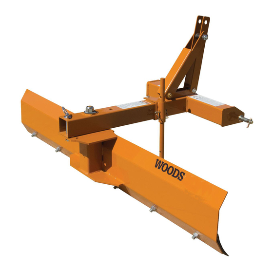
- Page 1 REAR BLADE & LANDSCAPE RAKE RBS54, RBS60, RBS72 LRS52, LRS60, LRS72 RBS60P, RBS72P, RBS84P LRS72P, LRS84P, LRS96P...
- Page 2 TO THE OWNER: Read this manual before operating your Woods equipment. The information presented will prepare you to do a better and safer job. Keep this manual handy for ready reference. Require all operators to read this manual carefully and become acquainted with all adjustment and operating procedures before attempting to operate.
-
Page 3: Table Of Contents
TABLE OF CONTENTS INTRODUCTION ......INSIDE FRONT COVER SPECIFICATIONS..........4 GENERAL INFORMATION . -
Page 4: Introduction
SPECIFICATIONS RBS54 RBS60P LRS52 LRS72P Models RBS60 RBS72P LRS60 LRS84P RBS72 RBS84P LRS72 LRS96P Unit Weight (Pounds) 134, 142, 156 268, 288, 308 156, 168, 186 264, 288, 311 Horse Power 30 HP Max 20 - 45 HP 30 HP Max... -
Page 5: Safety Rules
SAFETY RULES ATTENTION! BECOME ALERT! YOUR SAFETY IS INVOLVED! from being run over or crushed. Keep foldable Safety is a primary concern in the design and ROPS systems in “locked up” position at all times. manufacture of our products. Unfortunately, our efforts to provide safe equipment can be wiped ... - Page 6 SAFETY RULES ATTENTION! BECOME ALERT! YOUR SAFETY IS INVOLVED! disengage power to equipment, lower the 3-point (Safety Rules continued from previous page) hitch and all raised components to the ground, Do not stop, start, or change directions sud- operate valve levers to release any hydraulic pres- denly on slopes.
-
Page 7: Safety Decals
SAFETY & INSTRUCTIONAL DECALS ATTENTION! BECOME ALERT! YOUR SAFETY IS INVOLVED! Safety 7 MAN1047 (Rev. 4/15/2014) - Page 8 Replacement safety decals can be ordered free from your Woods dealer. To locate your nearest dealer, check the Dealer Locator at www.WoodsEquipment.com, or in the United States and Canada call 1-800-319-6637.
-
Page 9: Operation 9
OPERATION The operator is responsible for the safe operation of 3. Connect tractor top link by inserting tractor clevis this equipment. Operators must be instructed in and be pin into top hitch point on rear blade frame capable of the safe operation of the equipment, its assembly and secure (Figure 1). - Page 10 When using the rake tool, you may need to adjust the tail wheels after adjusting pitch to maintain the desired working depth. Position 3-point lift arm sway blocks or tighten sway chains to eliminate side sway. Install side braces if nec- essary.
- Page 11 Backfilling Parking Stand Placement (Optional) Reverse blade for backfilling ditches or trenches (see Assembly Reversing). 1. Assemble parking stand holder (1) toward center of The rake may also be used in light backfilling applica- frame assembly using 3/8 hex head cap screw (3), tions.
- Page 12 TAIL WHEEL ADJUSTMENT (OPTIONAL) TAIL WHEEL ADJUSTMENT (OPTIONAL) (STANDARD LANDSCAPE RAKE ONLY) (PREMIUM LANDSCAPE RAKE ONLY) 1. Yoke & wheel assembly 1. Yoke & wheel assembly 2. Tail wheel arm 2. Tail wheel arm 3. 1/2” Thick spacer 3. 1/2” Thick spacer 4.
- Page 13 PRE-OPERATION CHECK LIST (Owner’s Responsibility Before Each Use) ___ Review and follow all safety rules and safety decal instructions on pages 5 through 8. ___ Check that all safety decals are installed and in good condition. Replace if damaged. ___ Check that all hardware is properly installed and secured.
-
Page 14: Maintenance
MAINTENANCE The information in this section is written for operators REPLACING BLADE CUTTING EDGE who possess basic mechanical skills. If you need help, your dealer has trained service technicians available. Remove Cutting Edge For your protection, read and follow all safety informa- 1. - Page 15 Inspect machine and replace worn or damaged ● parts. ● Sand down scratches and the edges of areas of Rake tine missing paint and coat with Woods spray paint of Rake tine beam matching color (purchase from your Woods Tine clamp channel dealer). Carriage bolt Replace any safety decals that are missing or not ●...
-
Page 16: Assembly
Blade and Rake Assembly Assembly of this Rear Blade/Landscape Rake is the Blade and Rake Assembly (Standard) responsibility of the WOODS dealer. It should be deliv- 1. Assemble frame assembly onto threaded stud on ered to the owner completely assembled, lubricated moldboard or tine beam assembly and secure with and adjusted for normal cutting conditions. - Page 17 Blade Assembly (Premium) Install hitch pin (16) through hole in frame and into desired hole in pivot assembly. 1. Remove clamp channel (4) from pivot assembly 4. Assemble left and right mast plates (8 & 9) to frame (3). Insert clamp channel into main channel on assembly (1) using 1/2 NC x 3-1/2 hex cap screws back of moldboard (2).
- Page 18 Tail Wheel Installation (Optional) (Landscape Rake Only) 1. Remove landscape rake from tractor 3-point lift arms if attached. 2. Roll landscape rake over with tines pointing upward. 3. Place jack stands or suitable blocking device under tine beam to raise tine beam approximately 8 to 10 inches.
- Page 19 Quick Hitch Bushing Kit (Optional) Parking Stand (Optional Assembly 1. Assemble parking stand holder (1) toward center of frame assembly using 3/8 NC hex cap screw (3), 3/8 flat washers (4) and secure with 3/8 NC hex nut (5). Do not allow parking stand holder to cover any portion of safety decal.
- Page 20 Category 0 / 1 Hitch Pin Kit (Optional) Assemble one end plate (2) to each end of blade using two carriage bolts (3) and flange lock nuts (4) on each 1. Remove existing hitch pins. end plate. 2. Place hitch pin (1) through rear blade assembly. Skid Shoe Kit (Optional) 3.
- Page 21 Skid Shoe Kit (Optional) Remove plow bolts from each end of cutting edge. Attach right and left skid shoe brackets (3 & 4) to rear of moldboard with plow bolts (8), washers (9), and lock nuts (10) supplied in kit. Top of skid shoe brackets should angle slightly toward edge of blade.
-
Page 22: Dealer Check Lists
DEALER CHECK LISTS PRE-DELIVERY CHECK LIST DELIVERY CHECK LIST Inspect the equipment thoroughly after assembly to ___ Show customer how to make adjustments. ensure it is set up properly before delivering it to the ___ Instruct customer how to lubricate and explain customer. -
Page 23: Parts
PARTS INDEX REAR BLADE & LANDSCAPE RAKE RBS54, RBS60, RBS72 LRS52, LRS60, LRS72 RBS60P, RBS72P, RBS84P LRS72P, LRS84P, LRS96P RBS & LRS STANDARD ASSEMBLY ....... . . 24 - 25 RBS PREMIUM ASSEMBLY . - Page 24 RBS54, RBS60 & RBS72 ASSEMBLY LRS52, LRS60 & LRS72 ASSEMBLY 24 Parts (Rev. 11/10/2014) MAN1047 (Rev. 4/15/2014)
- Page 25 RBS54, RBS60 & RBS72 ASSEMBLY LRS52, LRS60 & LRS72 ASSEMBLY PART DESCRIPTION PART DESCRIPTION 54982* A/R 1/2 NC x 2-3/4 Carriage bolt, GR5 1 103741154RP RBS54 Moldboard 3489* 1/2 NC x 3 HHCS, GR5 1 103741160RP RBS60 Moldboard 1637* 1/2 NC x 3-1/2 HHCS, GR5...
- Page 26 RBS60, RBS72 & RBS84 (PREMIUM) ASSEMBLY PART DESCRIPTION PART DESCRIPTION 1043076 Hitch frame 3699* 1/2 NC x 2 HHCS, GR5 103751160RP RBS60 Moldboard -OR- 1637* 1/2 NC x 3-1/2 HHCS, GR5 103751172RP RBS72 Moldboard -OR- 855* 1/2 Lock washer 103751184RP RBS84 Moldboard 11900* 1/2 NC Flange hex lock nut...
- Page 27 LRS72, LRS84 & LRS96 (PREMIUM) ASSEMBLY PART DESCRIPTION PART DESCRIPTION 1043076 Hitch frame 27635* A/R 1/2 NC x 3-1/2 Carriage bolt, GR5 103753172 LRS72 Tine beam -OR- 1637* 1/2 NC x 3-1/2 HHCS, GR5 103753184 LRS84 Tine beam -OR- 11900* A/R 1/2 NC Flange hex lock nut 103753196 LRS96 Tine beam 15007...
- Page 28 RBS & LRS PARKING STAND (OPTIONAL) PART DESCRIPTION 1037480 1 Parking stand kit (For Standard) -OR- 1037450 1 Parking stand kit (For Premium) 1037481 1 Parking stand mounting bracket (For Standard) -or- 1037451 1 Parking stand mounting bracket (For Premium) 1021062RP 1 Parking stand 13927* 1 3/8 NC x 3-3/4 HHCS, GR5 (Standard) 20375* 1 3/8 NC x 4-1/4 HHCS, GR5 (Premium)
- Page 29 LRS TAIL WHEEL (OPTIONAL) PART DESCRIPTION 1037437 Tail wheel kit, LRS (Standard) 1 1037434RP Tail wheel arm 2 1037435RP Tail wheel clevis yoke 65129 Pipe, SCH 40 x .50, Spacer 66965 Wheel, 7.75 x 3.5 x .75 (Includes bearings item 5) 65577 Flange bearing, .75 x 1.415 29368...
- Page 30 LRS TAIL WHEEL (PREMIUM) (OPTIONAL) PART DESCRIPTION A 1037589RP Tail wheel kit, LRS (Premium) 1 1037534RP Tail wheel arm 2 1008032RP Tail wheel clevis yoke 65129 Pipe, SCH 40 x .50, Spacer 65130 Pipe, SCH 40 x 1.00, Spacer 19754 Wheel, 10.0 x 3.25 x .75, Pneum (Includes bearings items 6 &...
- Page 31 18300 PREMIUM SKID SHOE KIT (OPTIONAL) PART DESCRIPTION 18300 Skid shoe kit (Premium) ----- Blade assembly 27586RP Skid & shaft assembly 3 1005328RP Bracket, skid shoe right (not shown) 4 1005329RP Bracket, skid shoe left 52854 Sleeve, 1.28 x 1.66 x .75 27542 Pin, klik 7/16 x 2 Washer, flat 1-1/4 standard...
-
Page 32: Bolt Torque Chart
BOLT TORQUE CHART Always tighten hardware to these values unless a different torque value or tightening procedure is listed for a specific application. Fasteners must always be replaced with the same grade as specified in the manual parts list. Always use the proper tool for tightening hardware: SAE for SAE hardware and Metric for metric hardware. Make sure fastener threads are clean and you start thread engagement properly. -
Page 33: Bolt Size Chart & Abbreviations
BOLT SIZE CHART NOTE: Chart shows bolt thread sizes and corresponding head (wrench) sizes for standard SAE and metric bolts. SAE Bolt Thread Sizes 5/16 Metric Bolt Thread Sizes 10MM 12MM 14MM 16MM 18MM ABBREVIATIONS AG .............. Agriculture MPa............Mega Pascal ASABE ....American Society of Agricultural &... -
Page 34: Product Warranty
The limited warranty covers any defects in the material and/or workmanship. Following the proper, recommended installation by an authorized Woods Dealer and normal use of a Woods mounting and backhoe or loader, if a tractor incurs damage resulting from the attachment, Woods will cover the existing tractor warranty in the event the manufacturer voids its tractor warranty because of the attachment. - Page 35 Woods logo are trademarks of Woods Equipment Company. All other trademarks, trade names, or service marks not owned by Woods Equipment Company that appear in this manual are the property of their respective companies or mark holders. Specifications subject to change without notice.
- Page 36 Woods logo are trademarks of Woods Equipment Company. All other trademarks, trade names, or service marks not owned by Woods Equipment Company that appear in this manual are the property of their respec- tive companies or mark holders. Specifications subject to change without notice.
Need help?
Do you have a question about the RBS54 and is the answer not in the manual?
Questions and answers