Table of Contents
Advertisement
Quick Links
Technical Specifications
Installation &
Maintenance Manual
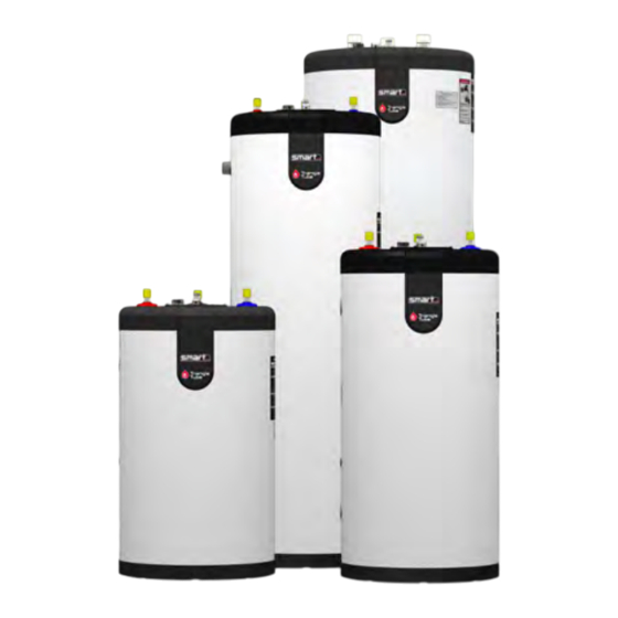
smart
30 - 4 0 - 50 - 6 0 - 80 - 10 0 - 120
INDI RECT FI RE D WATER HEATE R
WARNING
This document is intended to be used
by a factory trained and qualified
heating contractor or service technician
only. Read all Instructions within this
document and within the relevant Boiler
Installation and Maintenance Manual
before proceeding. It is recommended
to follow the procedures in the steps
given. Skipping or missing procedural
steps could result in substantial property
damage, serious injury, or death.
•
When receiving the SMART unit, any claims for damage or shortage in shipment must be filed imme-
diately against the transportation company by the consignee.
•
Customer must register unit within sixty (60) days of installation in order to gain warranty coverage.
See Warranty Card for details.
•
Leave all documentation received with appliance with the owner for future reference.
•
Installation and service should only be performed by a qualified installer or service technician.
•
Installations and service should be performed by a licensed plumber or gas fitter in the Common-
wealth of Massachusetts.
A1010024-661A0300 ■ G - 06/2023
2010-49
316
NOTICE
Low Lead Content
NSF/ANSI 372
CAUTION
•
The heat transfer medium must be
water or other nontoxic fluid hav-
ing a toxicity rating or class of 1, as
listed in Clinical Toxicology of Com-
mercial Products, 5th edition.
•
The pressure of the heat transfer
medium must be limited to a max-
imum of 30 psig by an approved
safety or relief valve.
T H E
O R I G I N A L
I N N O V A T O R S
Advertisement
Table of Contents

Related Manuals for TriangleTube Smart 316


Summary of Contents for TriangleTube Smart 316
- Page 1 Technical Specifications Installation & Maintenance Manual Low Lead Content NSF/ANSI 372 smart 30 - 4 0 - 50 - 6 0 - 80 - 10 0 - 120 INDI RECT FI RE D WATER HEATE R WARNING CAUTION This document is intended to be used •...
-
Page 2: Table Of Contents
TABLE OF CONTENTS PRODUCT AND SAFETY INFORMATION ................V CHAPTER 1 - PRE-INSTALLATION ..................1 1.1. Codes Compliance .......................... 1 1.2. Codes Restrictions .......................... 1 1.3. Operating Restrictions ........................2 1.4. Potable DHW Water Quality Requirements .................3 1.5. Closed Loop Boiler Heating Water Quality Requirements ............3 1.6. - Page 3 TABLE OF CONTENTS CHAPTER 4 - WATER HEATER START-UP ............... 21 4.1. Filling the Inner (Domestic Water) Tank ..................21 4.2. Filling the Outer (Boiler Water) Tank ................... 21 4.3. Adjusting the Water Heater Thermostat ..................22 CHAPTER 5 - WATER HEATER MAINTENANCE ...............23 5.1.
- Page 4 INDEX OF ILLUSTRATIONS AND TABLES Fig. 1 - SMART Clearances - View from the Top ..................4 Fig. 2 - Standard Installation - Domestic Piping - SMART Series ............8 Fig. 3 - Optional Installation - Domestic Piping with Recirculation - SMART Series ......9 Fig.
-
Page 5: Product And Safety Information
PRODUCT AND SAFETY INFORMATION IMPORTANT SAFETY INFORMATION FOR DANGER THE HOMEOWNER AND THE INSTALLER Hot Water Can Scald! This manual contains important information for the installation, • Water temperatures over 125ºF can cause severe starting up and maintenance of the appliance. burns instantly or death from scalding. - Page 6 Triangle Tube reserves the right to change the technical characteristics, components and features of its products without prior notice. Check for an updated CAUTION version of this manual at www.triangletube.com. • To prevent damage to the inner tank, the Installer must: –...
-
Page 7: Chapter 1 - Pre-Installation
1, as lation Code. listed in Clinical Toxicology of Commercial The Triangle Tube Smart 316 indirect-fired water heaters Products, 5th Edition, and are exempt from the scope of ASME Section VIII, Division 1. -
Page 8: Operating Restrictions
CHAPTER 1 - PRE-INSTALLATION 1.3. Operating Restrictions NOTICE • Maximum domestic hot water temperature is 180ºF (82°C) for commercial applications and 160ºF (71°C) • Artificiality softened boiler/heating wa- for residential applications. ter from a salt based water softener is not •... -
Page 9: Potable Dhw Water Quality Requirements
CHAPTER 1 - PRE-INSTALLATION 1.4. Potable DHW Water Quality Require- ments During installation and during the annual maintenance, The domestic water supplied to the water heater must the water quality must be checked and if found outside be potable water that is free from contaminants, sedi- of the requirements, must be corrected. -
Page 10: Locating Water Heater
CHAPTER 1 - PRE-INSTALLATION 1.7. Locating Water Heater When using antifreeze in the heating system circula- tor sizing must be considered because of the increase • This water heater is not intended for outdoor instal- viscosity of the glycol mixture, a higher head circulator lations. -
Page 11: Chapter 2 - Installation - Piping
CHAPTER 2 - INSTALLATION - PIPING 2.1. Temperature & Pressure (T&P) Relief 2.1.2 Commonwealth of Massachusetts Installation Valve In the Commonwealth of Massachusetts and in all jurisdictions requiring a vacuum breaker to be CAUTION installed on the domestic cold water inlet, follow To reduce risk of excessive pressures and these requirements : temperatures in the water heater, install tem-... -
Page 12: Drain Valve
CHAPTER 2 - INSTALLATION - PIPING 2.2. Drain Valve 2.6. Vacuum Breaker No drain valve is supplied with the unit. For information Installing a vacuum breaker (Watts N36-M1 or equiv- on draining the tank see page 23. alent) on the domestic cold water inlet will prevent damage to the inner tank if a negative pressure is de- 2.2.1 Standard Installation veloped in the domestic supply line. -
Page 13: Thermostatic Mixing Valve
CHAPTER 2 - INSTALLATION - PIPING 2.11. Multiple Water Heater Systems • When the water supply pressure is higher than 70 psig, it is recommended to install a pressure reduc- • Parallel Pipe Recirculation Systems - Manifold recircu- ing valve on cold water supply line to prevent wa- lation return to all water heaters. -
Page 14: Boiler Piping
CHAPTER 2 - INSTALLATION - PIPING 2.12. Boiler Piping • If antifreeze is used in the boiler system, local codes • All PEX tubing used to connect the indirect tank wa- may require a backflow preventer on cold water ter heater to the boiler must have an oxygen barrier. supply line. -
Page 15: Fig. 3 - Optional Installation - Domestic Piping With Recirculation - Smart Series
CHAPTER 2 - INSTALLATION - PIPING 12" min. Heat Trap Loop Recirculating (Optional) Loop Cold Water Inlet 12" min. Heat Trap Loop (Optional) Fig. 3 - Optional Installation - Domestic Piping with Recirculation - SMART Series 1. Shut-off valve 7. Drain valve 2. -
Page 16: Fig. 4 - Smart System Piping With Zone Valves (Non Domestic Priority)
CHAPTER 2 - INSTALLATION - PIPING Zone Valve Zone Valve Cold water inlet Fig. 4 - SMART System Piping with Zone Valves (Non Domestic Priority) Zone Circulator Zone Circulator Cold water inlet Fig. 5 - SMART System Piping with Zone Circulators 1. -
Page 17: Fig. 6 - Smart System Piping With 2-Port Zone Valves (Domestic Priority)
CHAPTER 2 - INSTALLATION - PIPING 2-Port Zone Valve (normally open) 2-Port Zone Valve (normally closed) Cold water inlet Fig. 6 - SMART System Piping with 2-Port Zone Valves (Domestic Priority) 3- Port Zone Valve Cold water inlet Fig. 7 - SMART System Piping with 3-Port Zone Valve (Domestic Priority) 1. -
Page 18: Fig. 8 - Multiple Smart Series Water Heater System Domestic Piping - Parallel
CHAPTER 2 - INSTALLATION - PIPING Check valve • Recommended for most applications. • Any one water heater tank thermo- Stop stat may be utilized to control system valve temperature. • Install automatic mixing valve at ei- ther the hot water outlet of the water heater system or at each hot water NOTICE fixture. -
Page 19: Fig. 9 - Multiple Smart Series Water Heater System Boiler Piping Reverse Return Balanced Flow
CHAPTER 2 - INSTALLATION - PIPING Fig. 9 - Multiple SMART Series Water Heater System Boiler Piping Reverse Return Balanced Flow Fig. 10 - Multiple SMART Series Water Heater System Boiler Piping - Manifold 1. Shut-off valves 6. Feed valve 2. -
Page 20: Chapter 3 - Installation - Wiring
CHAPTER 3 - INSTALLATION - WIRING 3.1. Wiring Requirements 3.3. Zone Valves WARNING Transformer must be sized for maximum load of all zone valves. Electrical shock hazard can cause substantial property damage, serious injury, or death. 3.4. Snap Set Connection Disconnect power before installing and/or servicing. -
Page 21: Fig. 12 - Smart Tank Thermostat Connected To Prestige Boiler Low Voltage Terminal
CHAPTER 3 - INSTALLATION - WIRING External Limit Mix Sensor Low Voltage Terminals Line Voltage Terminals Terminals Terminals Manual Auto System Modulation Outdoor Modbus Thermostat Sensor Signal Thermostat Sensor Sensor or Thermosta Aquastat L G N L G N L G N L G N L G N L G N... -
Page 22: Fig. 13 - Smart Tank Thermostat Connected To Instinct Boiler Low Voltage Terminal
CHAPTER 3 - INSTALLATION - WIRING External Limit Low Voltage Terminals Line Voltage Terminals Terminals Manual Auto System Modulation Outdoor Modbus Thermostat Sensor Signal Thermostat Sensor Sensor or Thermosta Aquastat N G L N G L N G L N G L N G POWER BOILER... -
Page 23: Fig. 14 - Typical 4-Wire Zone Valve Zoning, With Domestic Priority
CHAPTER 3 - INSTALLATION - WIRING V.A.C. High Voltage Transformer V.A.C. High Voltage (Power) Transformer (Power) V.A.C. V.A.C. Water Heater Thermostat Water Heater Zone Valve Snap-Set Thermostat Water Zone Valve Snap-Set Heater Water Zone Heater Zone Priority Priority Relay Relay Room Room Zone Valve... -
Page 24: Fig. 16 - Typical 4-Wire Zone Valve Zoning, Without Domestic Priority
CHAPTER 3 - INSTALLATION - WIRING V.A.C. High Voltage Transformer (Power) V.A.C. High Voltage V.A.C. Transformer (Power) Water Heater Thermostat V.A.C. Zone Valve Snap-Set Water Water Heater Heater Thermostat Zone Zone Valve Snap-Set Water Heater Zone Room Zone Valve Thermostat Zone 1 Room Zone Valve... -
Page 25: Fig. 18 - Typical Circulator Zoning With Domestic Priority
CHAPTER 3 - INSTALLATION - WIRING Thermostat Honeywell zone 1 Thermostat R845A Honeywell zone 1 Relay R845A Relay Circulator Circulator Zone 1 Zone 1 Thermostat zone 2 Thermostat zone 2 Circulator Circulator Zone 2 Zone 2 Water Heater Water Heater Thermostat Thermostat Snap-Set... -
Page 26: Fig. 20 - Priority Zone Circulator Wiring
CHAPTER 3 - INSTALLATION - WIRING Thermostat Honeywell zone 1 R845A Circulator Relay Note: Maximum of 4 total circulator zones when wir- ing 1 zone for priority Circulator Zone 1 Thermostat zone 2 High Voltage Low Voltage Priority Zone Circulator CIRC Circulator Zone 2... -
Page 27: Chapter 4 - Water Heater Start-Up
CHAPTER 4 - WATER HEATER START-UP DANGER 4.1. Filling the Inner (Domestic Water) Tank HOT WATER CAN SCALD! CAUTION Water temperature over 125ºF can cause se- • Never use water heater unless inner and vere burns instantly or death from scalds. outer tanks are completely filled with water. -
Page 28: Adjusting The Water Heater Thermostat
CHAPTER 4 - WATER HEATER START-UP 4.3. Adjusting the Water Heater Thermostat Water heater thermostat is factory set to its lowest tem- NOTICE perature. This may or may not be suitable for your needs. • Household water usage patterns will af- Turn thermostat knob clockwise to in- •... -
Page 29: Chapter 5 - Water Heater Maintenance
CHAPTER 5 - WATER HEATER MAINTENANCE 5.1. Maintenance Schedule 5.1.2 Homeowner monthly maintenance to in- clude: 5.1.1 Annual service by qualified service tech- ¨ Check for air. nician should include the following: • Manual air vent-open and close briefly to re- lease any air. -
Page 30: Preparation For Draining The Tank
CHAPTER 5 - WATER HEATER MAINTENANCE WARNING Water from opened drain valves, unions and other connections may be extremely hot. To 3. Close the DHW cold and hot valves. avoid substantial property damage, serious 4. Disconnect the cold DHW inlet and hot DHW outlet injury, or death: piping from the plumbing system in the building. -
Page 31: Chapter 6 - Replacement Parts
CHAPTER 6 - REPLACEMENT PARTS Thermostat Cover Plate Assembly Located Below Thermostat Cover Plate Assembly Fig. 22 - SMART Assembly Fig. 23 - SMART Cover Plate Assembly Item Part # Model Description P3KITAV02 Air vent, manual P3KITTH01 Aquastat - 160ºF residential SMRKIT200 Aquastat - 180ºF commercial P3KITBTM02... -
Page 32: Chapter 7 - Water Heater Specifications And Performances
CHAPTER 7 - WATER HEATER SPECIFICATIONS AND PERFORMANCES Temperature and Pressure Relief Valve Connection Hot Water Outlet Boiler Return Boiler Supply Fig. 24 - SMART Dimensions - Side View A1010024 - 661A0300 • G... -
Page 33: Fig. 25 - Smart Dimensions - Top View
CHAPTER 7 - WATER HEATER SPECIFICATIONS AND PERFORMANCES Temperature and Pressure Relief Valve Connection Cold Water Inlet Thermostat and Cover Plate Hot Water Outlet Air Vent Fig. 25 - SMART Dimensions - Top View Table 5 - SMART Water Heater Specifications SMART Model Capacity... - Page 34 CHAPTER 7 - WATER HEATER SPECIFICATIONS AND PERFORMANCES Table 6 - SMART Water Heater Performance at 200°F boiler water supply (140°F DHW outlet) Boiler Heating Continuous Peak Flow 1st Hour Flow Circulator Model Capacity Flow Gal./10 min. Gal./Hour Min. GPM Gal./Hour SMART 30 SMART 40...
- Page 35 NOTES A1010024 - 661A0300 • G...
- Page 36 Computerized sizing available from Triangle Tube • Available in capacities from 25,000 BTU/hr to 5,000,000 BTU/hr Triangle Tube - 1240 Forest Parkway, Suite 100, West Deptford NJ 08066 Tel: (856) 228 8881 - Fax: (856) 228 3584 - E-mail: info@triangletube.com...
Need help?
Do you have a question about the Smart 316 and is the answer not in the manual?
Questions and answers