Table of Contents
Advertisement
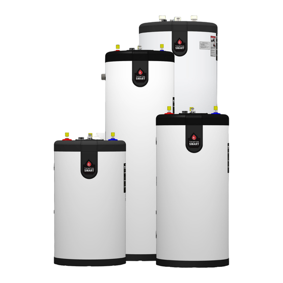
Installation & Maintenance Manual
•
When receiving the SMART unit, any claims for damage or shortage in shipment must be filed immediately against the
transportation company by the consignee.
•
Customer must register unit within sixty (60) days of installation in order to gain warranty coverage. See Warranty Card for
details.
•
Leave all documentation received with appliance with the owner for future reference.
•
Installation and service should only be performed by a qualified installer or service technician.
•
Installations and service should be performed by a licensed plumber or gas fitter in the Commonwealth of Massachusetts.
Before proceeding with installation and operation, read entire manual carefully. Failure to do so
Revision date : 06/25/19
Technical Specifications
30 - 40 - 50 - 60 - 80 - 100 - 120
Indirect Fired Water Heater
NOTICE
WARNING
can cause property damage or personal injury.
SMART
2010-49 Smart Manual
Advertisement
Table of Contents

Subscribe to Our Youtube Channel
Related Manuals for TriangleTube SMART Series


Summary of Contents for TriangleTube SMART Series
- Page 1 Technical Specifications Installation & Maintenance Manual SMART 30 - 40 - 50 - 60 - 80 - 100 - 120 Indirect Fired Water Heater NOTICE • When receiving the SMART unit, any claims for damage or shortage in shipment must be filed immediately against the transportation company by the consignee.
- Page 2 INTENTIONALLY LEFT BLANK...
-
Page 3: Table Of Contents
TABLE OF CONTENTS PRODUCT AND SAFETY INFORMATION ................. VII CHAPTER 1 - PRE-INSTALLATION ..................1 1.1. Codes Compliance .......................... 1 1.2. Codes Restrictions .......................... 1 1.3. Operating Restrictions ........................1 1.4. Locating Water Heater ........................2 1.5. Recommended Clearances ......................2 CHAPTER 2 - INSTALLATION - PIPING ................3 2.1. - Page 4 TABLE OF CONTENTS CHAPTER 5 - WATER HEATER MAINTENANCE ...............23 5.1. Maintenance Schedule ........................ 23 5.1.1 Annual service by qualified service technician should include the following: ....23 5.1.2 Homeowner monthly maintenance to include: ..............23 5.2. Filling Water Heater ........................23 5.3.
- Page 5 Fig. 12 - SMART System Piping with Zone Circulators ................12 Fig. 13 - Multiple SMART Series Water Heater System Boiler Piping Reverse Return Balanced Flow ..13 Fig. 14 - Multiple SMART Series Water Heater System Boiler Piping - Manifold ......... 13 Fig.
- Page 6 INTENTIONALLY LEFT BLANK...
-
Page 7: Product And Safety Information
PRODUCT AND SAFETY INFORMATION IMPORTANT SAFETY INFORMATION FOR DANGER THE HOMEOWNER AND THE INSTALLER Hot Water Can Scald! This manual contains important information with respect to the • Water temperatures over 125ºF can cause severe installation, starting up and maintenance of the appliance. burns instantly or death from scalding. - Page 8 Check for an updated version of this manual at www.triangletube.com. – Relieve primary system pressure below 15 psig prior to draining inner tank.
-
Page 9: Chapter 1 - Pre-Installation
45 psig. NOTICE • Water quality limitations (based on E.P.A National SMART Series water heaters will absorb less Secondary Drinking Water Regulations): than 200,000 BTU/hr when domestic wa- – Chloride, less than 150 ppm or mg/l ter outlet temperature is 210ºF and boil- –... -
Page 10: Locating Water Heater
12” minimum. placed under the water heater. • Refer to boiler manual for boiler clearances. • The SMART Series Water Heaters are designed for vertical installation only. Wall 12” Minimum Water Heater Fig. 1 - SMART Clearances - View from the Top... -
Page 11: Chapter 2 - Installation - Piping
CHAPTER 2 - INSTALLATION - PIPING 2.1. Temperature & Pressure (T&P) Relief 2.1.1 Standard Installation Valve • Install T&P relief valve in the Auxiliary connection located behind the air vent on the top of the water CAUTION heater (Refer to Fig. 2 on page 7). To reduce risk of excessive pressures and temperatures in the water heater, install tem- •... -
Page 12: Drain Valve
CHAPTER 2 - INSTALLATION - PIPING 2.2. Drain Valve 2.5. Water Hammer Drain valve and fittings are supplied by others. Dishwashers, clothes washers and fast-closing positive shut-off valves incorporated in the system all contrib- 2.2.1 Standard Installation ute to creating water shock. Install a water hammer ar- rester to prevent damage to pipes and appliances. -
Page 13: Thermostatic Mixing Valve
CHAPTER 2 - INSTALLATION - PIPING 2.10. Recirculation Piping. • If copper pipe is used for domestic water connections, first solder pipe to a threaded adapter and then screw • T&P relief valve must be installed in run (straight adapter into cold water inlet on top of water heater. through leg) of tee located at domestic hot water Inlet connection contains an internal plastic dip tube outlet of water heater. -
Page 14: Boiler Piping
CHAPTER 2 - INSTALLATION - PIPING 2.12. Boiler Piping • If antifreeze is used in the boiler system, local codes • If plastic pipe is used for boiler water piping, it must may require a backflow preventer on cold water have a maximum oxygen diffusion rate of 0.1 mg/ supply line. -
Page 15: Fig. 2 - Standard Installation - Domestic Piping - Smart Series
Cold Water Inlet 12" min. Heat Trap Loop (Optional) Fig. 3 - Standard Installation - Domestic Piping with Recirculation - SMART Series 1. Shut-off valve 7. Drain valve 2. Recirculation Circulator 8. Thermal expansion tank (potable) 3. Flow Check Valve 9. -
Page 16: Fig. 4 - Optional Installation - Domestic Piping With Recirculation - Smart Series
Inlet 12" min. Heat Trap Loop (Optional) Fig. 4 - Optional Installation - Domestic Piping with Recirculation - SMART Series 1. Shut-off valve 6. Backflow preventer or pressure reducing valve(*) 2. Recirculation Circulator 7. Drain valve 3. Flow Check Valve 8. -
Page 17: Fig. 5 - Drain Tube Assembly - Commonwealth Of Massachussets
Heat Trap (Optional) Loop (Optional) Cold Water Inlet Fig. 6 - Commonwealth of Massachussets - Domestic Piping SMART Series 1. Shut-off valves Vacuum breaker T&P relief valve 10. Mixing valve (*) Unions 11. Dip tube - Draining per Chart 1 Backflow preventer or pressure reducing valve (*) (*) Optional devices may be required by local codes. -
Page 18: Fig. 7 - Smart System Piping With 3-Port Zone Valve (Domestic Priority)
CHAPTER 2 - INSTALLATION - PIPING 3- Port Priority Valve Cold water inlet Fig. 7 - SMART System Piping with 3-Port Zone Valve (Domestic Priority) 2-Port Priority Valve (normally open) 2-Port Priority Valve (normally close) Cold water inlet Fig. 8 - SMART System Piping with 2-Port Zone Valves (Domestic Priority) 1. -
Page 19: Fig. 9 - Smart System Piping With Zone Valves (Non Domestic Priority)
CHAPTER 2 - INSTALLATION - PIPING Fig. 9 - SMART System Piping with Zone Valves (Non Domestic Priority) Fig. 10 - SMART System Piping with Zone Circulators 1. Shut-off valves 6. Feed valve 2. Circulator 7. Air separator 3. Flow check valve 4. -
Page 20: Fig. 11 - Multiple Smart Series Water Heater System Domestic Piping - Parallel
• Each tank should be piped with a drain as shown in Fig. 2 on page 7 Fig. 11 - Multiple SMART Series Water Heater System Domestic Piping - Parallel • Recommended for applications in which there is a large water consump- tion in short period of time. -
Page 21: Fig. 13 - Multiple Smart Series Water Heater System Boiler Piping Reverse Return Balanced Flow
CHAPTER 2 - INSTALLATION - PIPING Fig. 13 - Multiple SMART Series Water Heater System Boiler Piping Reverse Return Balanced Flow Fig. 14 - Multiple SMART Series Water Heater System Boiler Piping - Manifold 1. Shut-off valves 6. Feed valve 2. - Page 22 INTENTIONALLY LEFT BLANK...
-
Page 23: Chapter 3 - Installation - Wiring
CHAPTER 3 - INSTALLATION - WIRING 3.1. Wiring Requirements 3.3. Zone Valves WARNING Transformer must be sized for maximum load of all zone valves. Electrical shock hazard can cause substantial property damage, serious injury, or death. 3.4. Snap Set Connection Disconnect power before installing and/or servicing. -
Page 24: Fig. 16 - Typical 4-Wire Zone Valve Zoning, With Domestic Priority
CHAPTER 3 - INSTALLATION - WIRING V.A.C. High Voltage Transformer V.A.C. High Voltage (Power) Transformer (Power) V.A.C. V.A.C. Water Heater Thermostat Water Heater Zone Valve Snap-Set Thermostat Water Zone Valve Snap-Set Heater Water Zone Heater Zone Priority Priority Relay Relay Room Room Zone Valve... -
Page 25: Fig. 18 - Typical 4-Wire Zone Valve Zoning, Without Domestic Priority
CHAPTER 3 - INSTALLATION - WIRING V.A.C. High Voltage Transformer (Power) V.A.C. High Voltage V.A.C. Transformer (Power) Water Heater Thermostat V.A.C. Zone Valve Snap-Set Water Water Heater Heater Thermostat Zone Zone Valve Snap-Set Water Heater Zone Room Zone Valve Thermostat Zone 1 Room Zone Valve... -
Page 26: Fig. 20 - Typical Circulator Zoning With Domestic Priority
CHAPTER 3 - INSTALLATION - WIRING Thermostat Honeywell zone 1 Thermostat R845A Honeywell zone 1 Relay R845A Relay Circulator Circulator Zone 1 Zone 1 Thermostat zone 2 Thermostat zone 2 Circulator Circulator Zone 2 Zone 2 Water Heater Water Heater Thermostat Thermostat Snap-Set... -
Page 27: Fig. 22 - Priority Zone Circulator Wiring
CHAPTER 3 - INSTALLATION - WIRING Thermostat Honeywell zone 1 R845A Circulator Relay Note: Maximum of 4 total circulator zone when wiring 1 zone for priority Circulator Zone 1 Thermostat zone 2 Low Voltage High Voltage Priority Zone Circulator CIRC Circulator Zone 2 Water Heater... - Page 28 INTENTIONALLY LEFT BLANK...
-
Page 29: Chapter 4 - Water Heater Start-Up
CHAPTER 4 - WATER HEATER START-UP DANGER 4.1. Filling the Inner (Domestic Water) Tank HOT WATER CAN SCALD! CAUTION Water temperature over 125ºF can cause se- • Never use water heater unless inner and vere burns instantly or death from scalds. outer tanks are completely filled with water. -
Page 30: Adjusting The Water Heater Thermostat
Recheck water temperature at fau- cet after adjustment. • When adjusting thermostat, be sure boiler limit control is set a minimum of 20ºF higher. Temperature Temperature down Fig. 23 - SMART Series Temperature Knob... -
Page 31: Chapter 5 - Water Heater Maintenance
CHAPTER 5 - WATER HEATER MAINTENANCE 5.1. Maintenance Schedule 5.1.2 Homeowner monthly maintenance to in- clude: 5.1.1 Annual service by qualified service tech- ¨ Check for air. nician should include the following: • Manual air vent-open and close briefly to re- lease any air. -
Page 32: Draining Inner (Domestic Water) Tank
CHAPTER 5 - WATER HEATER MAINTENANCE 4. When draining is complete, close the hot water fau- WARNING cet and the domestic drain valve. Draining Inner Tank - Option 2 Water from opened drain valves, unions and other connections may be extremely hot. To 1. -
Page 33: Chapter 6 - Replacement Parts
CHAPTER 6 - REPLACEMENT PARTS Thermostat Cover Plate Assembly Located Below Thermostat Cover Plate Assembly Fig. 24 - SMART Assembly Fig. 25 - SMART Cover Plate Assembly Item Part # Model Description P3KITAV02 Air vent, manual P3KITTH01 Aquastat - 160ºF residential P3KITTH03 Aquastat - 194ºF commercial P3KITBTM02... -
Page 34: Chapter 7 - Water Heater Specifications And Performances
CHAPTER 7 - WATER HEATER SPECIFICATIONS AND PERFORMANCES Auxiliary Connection Hot Water Outlet Boiler Return Boiler Supply Fig. 26 - SMART Dimensions - Side View... -
Page 35: Fig. 27 - Smart Dimensions - Top View
CHAPTER 7 - WATER HEATER SPECIFICATIONS AND PERFORMANCES Auxiliary Connection Cold Water Inlet Thermostat and Cover Plate Hot Water Outlet Air Vent Fig. 27 - SMART Dimensions - Top View Table 2 - SMART Water Heater Specifications SMART Model Capacity Gal. - Page 36 CHAPTER 7 - WATER HEATER SPECIFICATIONS AND PERFORMANCES Table 3 - SMART Water Heater Performance at 200°F boiler water supply (140°F DHW outlet) Boiler Heating Continuous Peak Flow 1st Hour Flow Circulator Model Capacity Flow Gal./10 min. Gal./Hour Min. GPM Gal./Hour SMART 30 SMART 40...
- Page 40 Computerized sizing available from Triangle Tube • Available in capacities from 25,000 BTU/hr to 5,000,000 BTU/hr Triangle Tube - 1240 Forest Parkway, Suite 100, West Deptford NJ 08066 Tel: (856) 228 8881 - Fax: (856) 228 3584 - E-mail: info@triangletube.com A1006379 - 661A0300 • D...
Need help?
Do you have a question about the SMART Series and is the answer not in the manual?
Questions and answers