Table of Contents
Advertisement
Quick Links
Advertisement
Table of Contents

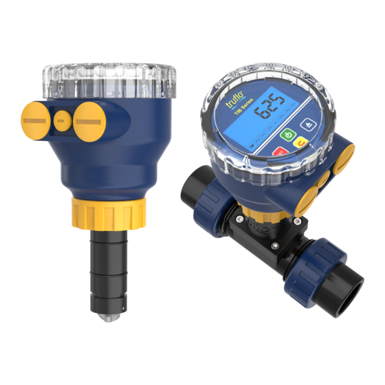
Summary of Contents for ICON Truflo TIB Series
- Page 1 — TIB Series ® Insertion Paddle Wheel Flow Meter Sensor Quick Start Manual Read the user's manual carefully before starting to use the unit. Producer reserves the right to implement changes without prior notice. 24-0407 © Icon Process Controls Ltd.
-
Page 2: Safety Information
Truflo products. Pressurized System Warning Sensor may be under pressure. Take caution to vent system WARNING prior to installation or removal. Failure to do so may result in equipment damage and/or serious injury. 24-0407 © Icon Process Controls Ltd. -
Page 3: Display Characteristics
-4°F to 190°F -20°C to 88°C PVDF -40°F to 240°F -40°C to 115°C 316SS -4°F to 190°F -20°C to 88°C Standards and Approvals RoHS Compliant See Temperature and Pressure Graphs for more information * Optional 24-0407 © Icon Process Controls Ltd. - Page 4 Superior Chemical And Wear Resistance vs PVDF Zirconium Ceramic Rotor | Bushings Up to 15x the Wear Resistance Integral Rotor Bushings Reduce Wear and Fatigue Stress 360º Shielded Rotor Design Eliminates Finger Spread No Lost Paddles vs. Competitor 24-0407 © Icon Process Controls Ltd.
-
Page 5: Installation
• DO NOT use any tools — threads may Locate the flow meter positioning tab is seated in the fitting notch. be damaged tab and clamp saddle notch. Ensure tab is parallel to flow direction. • Ensure meter is firmly in place 24-0407 © Icon Process Controls Ltd. -
Page 6: Installation Positions
Air Bubbles may be Present Air Bubbles may be Present Air Bubbles may be Present SEDIMENT* or AIR BUBBLES may be present *Maximum % of solids: 10% with particle size not exceeding 0.5mm cross section or length 24-0407 © Icon Process Controls Ltd. - Page 7 4" | DN100 125.0 | 33.0 4350.0 | 1149.0 °F °C 316SS 6" | DN150 230.0 | 60.0 7590.0 | 1997.0 PVDF 8" | DN200 315.0 | 82.0 10395.0 | 2735.0 316SS PVDF * Optional 24-0407 © Icon Process Controls Ltd.
-
Page 8: Unit Selection
5 (5 Secs, Default) Flow Alarm Delay ▶ Time Delay for Visual Alarm dt. 10 (10 Secs, Default) Reset Totalizer ▶ | Flow Totalizer Reset Enabled rESET.1 (Default) rESET.0 | Flow Totalizer Reset Disabled 24-0407 © Icon Process Controls Ltd. - Page 9 Change Digit Value STEPS DISPLAY OPERATION Home Screen ▶ Home Screen �� 3 Sec . High Alarm ▶ High Alarm Value Enter High Alarm Value Low Alarm ▶ Low Alarm Value Enter Low Alarm Value 24-0407 © Icon Process Controls Ltd.
-
Page 10: Battery Status Indicator
Low Voltage (Pilot BAT & Display Flashing) Sleep Settings STEPS DISPLAY OPERATION Home Screen ▶ Home Screen �� 3 Sec . Sleep Mode ▶ Sleep Mode Active Press again to deactivate sleep mode Dimensions (mm) 91.7 91.7 TIB Series 24-0407 © Icon Process Controls Ltd. - Page 11 Tap until pin is 50% out Small Pin Pin Hole Pull out Pull out Insert new paddle in flow meter Paddle Push in pin GENTLY tap Congratulations! approx. 50% Replacement procedure is complete! Ensure holes are aligned 24-0407 © Icon Process Controls Ltd.
-
Page 12: Battery Replacement
316 SS 1" - 4" TIB-PP-S Add Suffix - 6" - 24" TIB-PP-L ‘E’ - EPDM Seals 1" - 4" TIB-PF-S PVDF 6" - 24" TIB-PF-L PVDF Add Suffix - ‘E’ - EPDM Seals 24-0407 © Icon Process Controls Ltd. -
Page 13: Installation Fittings
8” SWOL8 • Easy to Install Glue-On Adapter 10” SWOL10 • Will Accept 12” SWOL12 Signet Flow Meter ® • 2”-24” Pipe Sizes • Easy to Install • Will Accept Signet Flow Meter ® 24-0407 © Icon Process Controls Ltd. - Page 14 Icon Process Controls Ltd for a period of one year from the date of sale of such products. Icon Process Controls Ltd obligation under this warranty is solely...


Need help?
Do you have a question about the Truflo TIB Series and is the answer not in the manual?
Questions and answers