
Subscribe to Our Youtube Channel
Related Manuals for Elo TouchSystems WALLABY PRO


Summary of Contents for Elo TouchSystems WALLABY PRO
- Page 1 ASSEMBLY INSTRUCTIONS, MERCHANT-FACING DISPLAY BRACKET KIT FOR WALLABY © Copyright 2023 Elo Touch Solutions, Inc. UM600659 Revision A...
- Page 2 Contents for Kit: E801367, Merchant-Facing Display Bracket Kit for Wallaby Hardware Screw, M4x3.5, Flat Head, Qty.8 “A” Cross Recess Screw, M4x6, Flat Head, Cross Qty.8 “B” Recess Screw, M4x8, Pan Head, Cross Qty.4 “C” Recess Arm Assembly Qty. 1 Cable tie, Mounting Plate Cover Plate Qty.
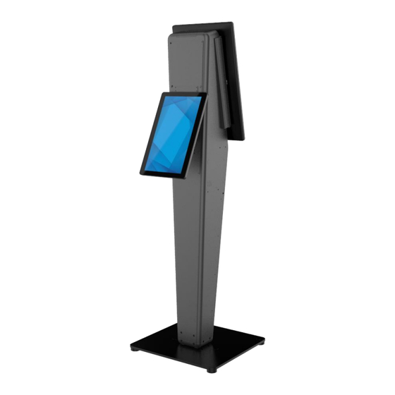
- Page 3 Note: Kit is compatible with both countertop and floor Landscape versions of Wallaby Pro. Portrait Remove rear cover of Wallaby Pro. Attach arm assembly to merchant-facing display VESA using four screws from bag “C”. Display can be oriented in either portrait or landscape orientation.
- Page 4 Upper position Lower position Attach mounting plate to arm in desired position using four Attach cover plate to unused opening using four screws from screws from bag “A”. bag “A”. Upper position is recommended for floor installations or installations on counters shorter than 36”. Lower position is recommended for installations on counters that are 36”...
- Page 5 Cable tie-downs Route display cables through arm and connect to display. Tie Install four screws from bag “B” into back of Wallaby Pro in down to arm using cable ties. Reinstall display cable covers. the locations shown, fully tightening until the screws bottom out.
- Page 6 Upper opening Cable routing Lower opening Pre-route display cables through rear openings in Wallaby Pro. Use Pre-hang mounting plate onto back of Wallaby Pro, upper opening for upper arm position, or use lower opening for lower engaging four screws from step 6 with keyholes in mounting arm position.
- Page 7 Install remaining four screws from bag “B” to secure mounting plate as Connect display cables to I-Series or compute module. shown. If powering the merchant-facing display using a DC power supply, an IEC C13 to AC adapter is required to plug the power supply into the Wallaby Pro internal power strip.
- Page 8 Learn more about Elo at EloTouch.com. Americas Europe (EMEA) Asia Pacific Tel +1 408 597 8000 Tel +32 16 930 136 Tel +86 (21) 3329 1385 EloSales.NA@elotouch.com EMEA.sales@elotouch.com EloAsia@elotouch.com The information in this document is subject to change without notice. Elo Touch Solutions, Inc. and its Affiliates (collectively “Elo”) makes no representations or warranties with respect to the contents herein, and specifically disclaims any implied warranties of merchantability or fitness for a particular purpose.
Need help?
Do you have a question about the WALLABY PRO and is the answer not in the manual?
Questions and answers