Table of Contents
Advertisement
Quick Links
Advertisement
Table of Contents

Related Manuals for Gaggenau KG260224CA


Summary of Contents for Gaggenau KG260224CA
- Page 1 Operating and assembly instructions KG 260 CA Gas cooker...
-
Page 2: Table Of Contents
Page 3 Preface Page 4 1. Important notes Page 5-6 1.1 For your safety Page 5 1.2 Operating for the first time Page 5 1.3 About use Page 6 2. Structure and operating principle Page 7-8 2.1 Structure Page 7 2.2 Special accessories... -
Page 3: For Your Safety
FOR YOUR SAFETY WARNING: If the information in this manual is not followed exactly, a fire or explosion may result causing property damage, personal injury or death. Do not store or use gasoline or other flammable vapors and liquids in the vicinity of this or any other appliance. -
Page 4: Warnings
This installation must conform with local codes or, in based on safety considerations. absence of local codes, with the National Fuel Gas 2. Do not forget that the unit becomes hot when in Code, ANSI Z 223.1 Current Issue. use. Common sense is important. Just because... -
Page 5: Preface
– Thanks to the novel installation method implemented, installation is child's play! To ensure that you will be able to use this appli- ance in all its diversity, read through the operating and assembly instructions conscientiously before operating it for the first time. -
Page 6: Important Notes
Technical modifications reserved. Only ever operate the appliance under supervision. Do not operate the appliance without pots and pans placed on it. Make sure that all the burner parts are 1.2 Operating for the first time correctly fitted. Before operating the appliance for the first time,... -
Page 7: About Use
Use the appliance to prepare meals only. It must not ignite. Ensure an adequate supply of air when be used to heat up the room in which it is installed. using a vapour extractor operating in the exhaust air mode. -
Page 8: Structure And Operating Principle
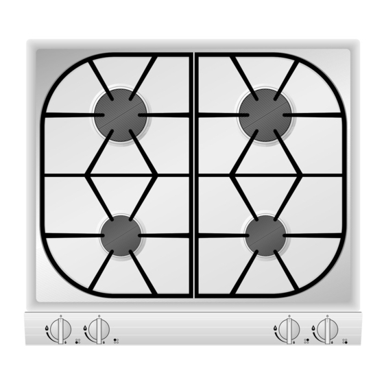
2 High burner, 9500 BTU (2.8 kW) 3 Normal burner, 6500 BTU (1.9 kW) 4 Control knob for the front left cooking position 5 Control knob for the rear left cooking position 6 Control knob for the rear right cooking position 7 Control knob for the front right cooking position Fig. -
Page 9: Operating Principle
The total rated thermal load amounts to: 32 000 BTU (9.4 kW) referred to H s * (gross calorific value) 28 600 BTU (8.4 kW) referred to H i (calorific value) The specified rated load is defined by installation of the fixed nozzles. -
Page 10: Operation
– Fully press in the control knob for the corresponding cooking position. This activates the ignition. Keep the control knob pressed! – Turn the control knob to the left to the “high" position. If the flame should not ignite within 2 to 4 seconds, turn the control knob further to the left to the “low"... -
Page 11: Cleaning And Care
(not on the control panel!). This will ensure an even surface and will keep Never use abrasive or caustic cleaning agents. your hob in a good condition for a long period of You should only clean the control panel and the time. -
Page 12: Maintenance
In the event of malfunctions, check whether the gas and electricity supply is in proper working order, i.e. the gas valve is open and the plug has been plugged into the socket. If the power supply is functioning correctly, but your... -
Page 13: Technical Data / Settings Table
Full burning 9500 BTU (2.8 kW) Low burning < 1900 BTU (0.56 kW) Technical modifications reserved. Gas connection: R 1/2’’ union nut for R 1/2’’ bracket to DIN 1999, conical-cylindrical Technical data, gas Countries Gas family Natural gas Propane gas... -
Page 14: Assembly Instructions
If the data should not agree, the appliance must be set to the required gas type and the available Technical modifications reserved. pressure. As this gas hob is not intended for connection to an exhaust gas system, pay attention to the applicable installation conditions. Note on ventilation:... - Page 15 If, after installation of the gas hob, not all poles can be isolated from the power by removing the plug, an isolating device with a contact gap of at least 3 mm must be permanently installed.
-
Page 16: Electrical Connection/Gas Connection
Make-Essex Model SX 229 NA-602 PSIG 1. Remove the aluminum cap from the top of the regulator. 2. Turn the cap over. It will have LP 10 stamped inside. 3. Replace the cap on the regulator. Make-Maxitrol Model RV 47 CL PSIG 1. -
Page 17: Nozzle Replacement
(see nozzle table). Fig. 10 The low setting nozzle is screwed in fully at the works, and so the lowest quantity is set. Replacing the low-setting nozzle 1 See table on Page 12 Proceed as follows: for details of nozzle settings. - Page 18 Checking functions The flames are adjusted correctly if no yellow tips are visible and if they do not go out when switching over swiftly from the high to the low setting. Fig. 11 Adjusting the primary air...
-
Page 19: Installing The Appliance
90° (Fig. 12). – Mark the centre of the recess exactly. Secure the longer securing rail on the rear edge and the shorter securing rail on the front edge of the recess. Make sure that the lugs of the securing... - Page 20 GAGGENAU HAUSGERÄTE GMBH 5551 McFADDEN AVENUE CARL-WERY-STR. 34 · 81739 MÜNCHEN HUNTINGTON BEACH, CA 92649 GERMANY Y (0 89) 45 90 - 03 Y (800) 828-9165 · FAX (714) 901-0979 FAX (0 89) 45 90 - 23 47 www.gaggenau-usa.com...
Need help?
Do you have a question about the KG260224CA and is the answer not in the manual?
Questions and answers