Table of Contents
Advertisement
Quick Links
Advertisement
Table of Contents

Related Manuals for Gaggenau KG491110


Summary of Contents for Gaggenau KG491110
- Page 1 Operation, Maintenance and Installation Manual KG 491 Gas Cooker...
-
Page 3: Table Of Contents
7. Wok Cookware Recommendations Page 11 8. Cleaning and Care Page 12-14 9. Maintenance Page 15 10. Trouble Shooting Page 16 11. Technical Data / Nozzle Table Page 17-19 12. Installation Instructions Page 20-29 Important Notes Page 20-21 Electrical Connection Page 21... - Page 4 • Maximum comfort and safety through electronic flame detection and automatic re-ignition Before operating your new appliance for the first time, please take your time to read through the manual conscientiously to get to know all its features. The manual contains important information for use, installation and care of the appliance.
-
Page 5: Important Notes
Do not operate the appliance without pots and pans of the gas supply companies and the regional placed on it. Make sure that all the burner parts are construction regulations. correctly fitted. Turn all control knobs to the OFF position before Caution: The appliance heats up during operation. -
Page 6: About Use
Use the appliance to prepare meals only. It must not pay attention to keeping to a minimum distance of be used to heat up the room in which it is installed. 50 mm between the cooking vessel and combustible surroundings. -
Page 7: Features
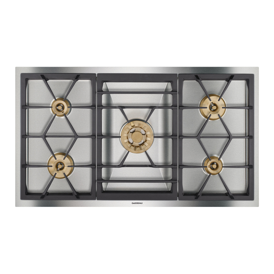
2. Features Features of the Appliance Pot grids (3 parts, the left and right part are identical) 2 Large (Wok) burner 3 Large burner 4 Normal burner Ventilation openings Control Knobs 6 Control knob for front left cooking zone 7 Control knob for rear left cooking zone... -
Page 8: Operating Principle
High The total rated thermal load amounts to: 17.0 kW referred to H s * (gross calorific value) 15.3 kW referred to H i (calorific value) The specified rated load is defined by installation of the fixed nozzles. -
Page 9: Operation
4. Operation Switching on Only light a burner if all burner parts are dry, and • Place a suitable pot or a pan on the corresponding assembled correctly. Otherwise, malfunctions may cooking position. occur or the appliance may switch off. - Page 10 Switching off Fully turn the control knob to the OFF position. The electronics of the appliance switch the gas supply off, if all control knobs are in the off position.
-
Page 11: Settings Table
Reheating Soup, casserole, vegetables in a sauce Switch to the high setting in order to reach the required temperature quickly. Then switch back to a lower setting. The output of the inner flame ring is the same on the normal, as well as the large burners. -
Page 12: Cookware Recommendations
6. Cookware Recommendations Pots with a diameter of less than 90 mm or more KG 491 Recommended Minimum than 280 mm / 320 mm for the large (WOK) pot diameter pot diameter burner should not be used. When using large pots,... -
Page 13: Wok Cookware Recommendations
Surplus oil drains off towards the middle. In next to no time, you obtain delicious roasted foods, the – The diameter is between 35 - 40 cm for 4 persons. pores in meat close and the meat stays soft and juicy. -
Page 14: Cleaning And Care
This change in color hand-warm. Never switch on the cooktop will not influence the use-value. while cleaning. Please thoroughly clean the appliance before operating it for the first time and after every use. - Page 15 (not on the control panel!). This will ensure an even surface and will keep • Important! Only clean the burner parts when your hob in a good condition for a long period of cold! time. • Make sure the burner parts are dry before assembly.
- Page 16 Burner Ring, cloth and detergent. Port openings must be kept free. Burner Head Use brass polish to keep the Be careful not to loose the small parts. (brass) original shiny surface. Wok Burner Head Clean with detergent and brush. Do not clean in a dishwasher.
-
Page 17: Maintenance
The cooktop cannot be used during a power failure. If the cooktop is being used when the power failure occurs, turn all of the burner control knobs to the OFF position. The cooktop will not turn back on after a power failure until all control knobs are first turned OFF and then turned back on again. -
Page 18: Trouble Shooting
• LP (propane) • LP (propane) gas: is the gas gas: is the gas tank empty? tank empty? Contact your Gaggenau after- Switch the appliance on again. Should the appliance still not work, sales service contact your Gaggenau after-sales service. -
Page 19: Technical Data / Nozzle Table
11. Technical Data / Nozzle Table Technical data (gas) Gas connection: R 1/2’’ union nut for R 1/2’’ bracket to DIN 1999, conical-cylindrical Burners: Normal burner Full burning 2.0 kW Technical data (electrical) Low burning 0.165 kW Large burner Rated consumption... - Page 20 BE CH CZ DK AT CH DE DE DK ES FI ES FI FR GB FR GB GR HU GR HU IE IS IE IS IT LU NL IT LU NO PL PL PT RU SE PT RU Gas family Natural gas...
- Page 21 BE CH CZ DK AT CH DE DE DK ES FI ES FI FR GB FR GB GR HU GR HU IE IS IE IS IT LU NL IT LU NO PL PL PT RU SE PT RU Gas family Natural gas...
-
Page 22: Installation Instructions
12. Installation Instructions Important Notes Please observe the general safety notes and the As this gas hob is not intended for connection to an important information in chapter 1. exhaust gas system, pay attention to the applicable installation conditions. installing technician is responsible for... -
Page 23: Electrical Connection
The mains connecting cable must at least more cooking positions are used, the higher the air correspond to type H 05 V2V2 3G 0.75 or it must be output level must be. correspondingly heat-resistant (at least 90 °C). -
Page 24: Preparing The Cabinet
Preparing the Cabinet Note: the appliance can be installed in a base • If the cabinet front is thicker than 26 mm, the front cabinet with a minimum width of 900 mm. The must be routed from the back to max. 26 mm on recess in the countertop will be slightly wider than an area of 80 x 470 mm. -
Page 25: Installing The Cooker
• Before installation, remove all styrofoam packaging from the control knobs and peel off the protective film. • Hold the support plate from the rear against the cabinet front (make sure the angled edge of the support plate is on the bottom), insert control knobs into the holes, secure from the rear with the nuts. -
Page 26: Installing The Spindles
There are four equal spindles and one that is longer: use the longer spindle for the wok burner (centre control knob). • The gas taps of the burners must be in the off position (flat side to the top). Slide the spindles on the gas taps. -
Page 28: Gas Connection
115 °K. If a flexible line is used, it must be laid in such a way that it cannot come into contact with moving parts of the kitchen element (e.g. drawer). -
Page 29: Nozzle Replacement
• Remove the cover plate from the gas taps. • Turn the gas tap with the plastic part so that the recess is above the nozzle. Screw out nozzle and take nozzle out with small pliers. - Page 30 • Detach the safety spring on the supply lines. Leave the electrode connected. Unscrew the burners from the trough (Torx T20) and pull off the inner main nozzle burner from both supply lines. • Carefully pull off both main nozzles together with the O-ring by hand.
- Page 31 Checking functions The flames are adjusted correctly if no yellow tips are visible and if they do not go out when switching over swiftly from the high to the low setting. Please do not forget to stick the new adhesive label...
- Page 32 GAGGENAU HAUSGERÄTE GMBH CARL-WERY-STR. 34 · D - 81739 MÜNCHEN (0 89) 45 90 - 03 FAX (0 89) 45 90 - 23 47 www.gaggenau.com...
Need help?
Do you have a question about the KG491110 and is the answer not in the manual?
Questions and answers