Table of Contents
Advertisement
Available languages
Available languages
Quick Links
Operating instructions
2/2 SOLENOID OPERATED,
HYDRAULIC SCREW-IN POPPET-TYPE VALVE, PILOTED,
DESIGNED FOR USE IN EXPLOSIVE ATMOSPHERES
SD3EX-B2, SD3EX-C2
SD3EX-B2
Important!
Read the instructions before using the product.
Save the instructions for future reference.
If the operating instructions are lost, new ones can be found on the ARGO-HYTOS website
The following is the authorised translation of original operating instruction SD3EX-B2, SD3EX-C2
No.14067_2cz_08/2024, issued by the manufacturer:
ARGO-HYTOS s.r.o.
Dělnická 1306, CZ 543 01 VRCHLABÍ
Info.cz@argo-hytos.com
www.argo-hytos.com
Operating instructions_SD3EX-B2_SD3EX-C2_14067_2en_08/2024
SD3EX-C2
2O2
2L2
+ 420 499 403 111
EN
www.argo-hytos.com
Page 1
Advertisement
Chapters
Table of Contents

Related Manuals for Voith ARGO HYTOS SD3EX-B2


Summary of Contents for Voith ARGO HYTOS SD3EX-B2
- Page 1 Operating instructions 2/2 SOLENOID OPERATED, HYDRAULIC SCREW-IN POPPET-TYPE VALVE, PILOTED, DESIGNED FOR USE IN EXPLOSIVE ATMOSPHERES SD3EX-B2, SD3EX-C2 SD3EX-B2 SD3EX-C2 Important! Read the instructions before using the product. Save the instructions for future reference. www.argo-hytos.com If the operating instructions are lost, new ones can be found on the ARGO-HYTOS website The following is the authorised translation of original operating instruction SD3EX-B2, SD3EX-C2 No.14067_2cz_08/2024, issued by the manufacturer: ARGO-HYTOS s.r.o.
-
Page 2: Declaration Of Conformity
Declaration of conformity Page 2 www.argo-hytos.com Operating instructions_SD3EX-B2_SD3EX-C2_14067_2en_08/2024... - Page 3 Page 3 www.argo-hytos.com Operating instructions_SD3EX-B2_SD3EX-C2_14067_2en_08/2024...
- Page 4 Page 4 www.argo-hytos.com Operating instructions_SD3EX-B2_SD3EX-C2_14067_2en_08/2024...
-
Page 5: Table Of Contents
Mandatory traceability Based on legislative requirements, all operators in the logistics chain, from the manufacturer of the certified Ex solenoid coil to the end user of the complete equipement, are obliged to make and maintain traceability records of Ex products, enabling, if necessary, the withdrawal of products of certain serial numbers from the market due to defects of non-conformities, endangering safety of use in an explosive atmosphere. -
Page 6: Overview Of Signal Words And Warning Signs Used In The Text
An overview of signal words and warning signs used in the text Signal word combined with a warning sign used to signify that a dangerous situation which could result in DANGER death or serious injury is imminent. Signal word combined with a warning sign used to signify the occurrence of a potentially dangerous situation WARNING that could result in death or serious injury if not avoided. -
Page 7: Valve Protection Against Intitiation Of Explosion In Explosive Atmosphere
Area of application EQUIPMENT - GROUP I – MINES EQUIPMENT - GROUP II (IIG) - GAS EQUIPMENT - GROUP III (IID) - DUST Category M1– Zone 0 - Zone 20 - IIA (propane) IIIA (combustible particles) Categorie M2 Zone 1 Zone 21 (the device remains IIB (ethylene) -
Page 8: Applicable Legislation And Standards
2.4 Applicable legislation and standards The valve complies with the relevant requirements of legislation and standards: Directive 2014/34/EU (harmonized NV 116/2016) Equipment for potentially explosive atmospheres (ATEX) IECEx OD 009 Operational Document The following standards were used to assess the conformity of the electrical part: CENELEC EN IEC 60079-0 Explosive atmospheres –... -
Page 9: Local Certification
2.5 Local certification 2.5.1 Great Britain The product is subject to certification, carried out by entities notified to the EU in accordance with EU legislative regulations and standards, until 31 December 2027. EU certification continues to apply to Northern Ireland. Legislative regulation: Directive 2014/34/EU (ATEX), Regulation 2016: Equipment and Protective Systems Intended for use in Potentially Explosive Atmospheres... -
Page 10: Risks And Limitations Of Product Use
3. Risks and limitations of product use 3.1 Risks associated with operating in explosive atmospheres Explosive atmosphere type and zone The valve must not be used outside the specified range (see paragraph 1Product use ), in particular it is not DANGER intended for equipment category M1group l (mines) zone 0 group II (gases) and zone 20 group III (dust). -
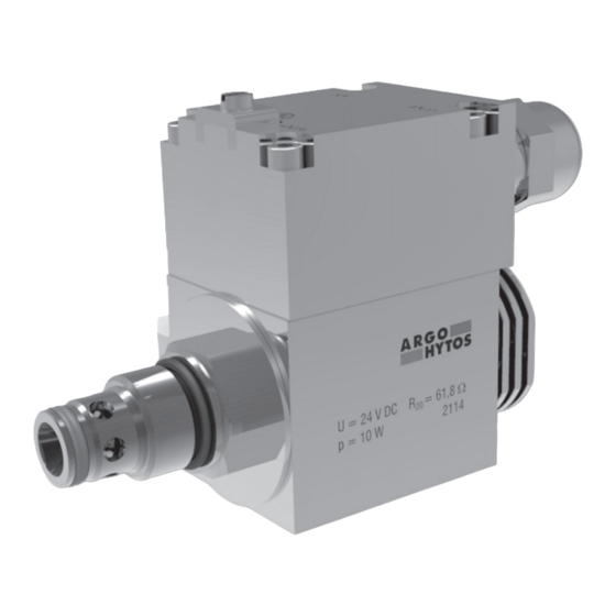
Page 11: Product Description
4. Product description The hydraulic part of the valve consists of a steel bush (A) with radial inlets of port 2 and axial outlets of port 1. A hardened poppet moves inside the seat and is held in its basic position by a return spring. The poppet is repositioned by fluid pressure after opening/closing the control stage, operated by an explosion-proof certified solenoid (B). -
Page 12: Basic Technical Parameters
4.4 Basic technical parameters Parameter Unit Value Valve type SD3EX-B2 SD3EX-C2 Valve connection thread 7/8-14 UNF 1-1/16-12 UN Maximum pressure bar (PSI) 420 (6092) 350 (5076) Maximum flow l/min (GPM) 75 (19.8) 150 (39.6) Pressure losses as a function of flow rate bar (PSI) graph ∆p = f (Q) Fluid temperature... -
Page 13: Valve Characteristics
4.6 Valve characteristics Characteristics measured at = 32 mm /s (156 SUS) Valve SD3EX-B2 Operating limits (p-Q) Pressure drop as a function of flow rate (∆p-Q) Ambient temp 70 °C (158 °F), voltage U -10 % (24 V DC), power P 10 W (6530) 450 (87.0) - Page 14 Ordering code SD3EX - xxxxx Screw-in spool type, solenoid operated directional control valve, designed for potentially explosive atmospheres Threaded screw-in cavity type cavity B2 (VC10-2) with thread 7/8-14 UNF cavity C2 (VC12-2) with thread 1-1/16-12 UN High performance Valve connection Nominal supply voltage DC voltage 01200...
-
Page 15: Target Group Of Users
6. Target group of users All of the above activities related to this valve, in particular installation and connection to the hydraulic circuit, require specialist technical knowledge and experience in the field of hydraulics. The minimum level of competence required is CETOP level 2. This level is generally defined as performing a variety of activities that require an understanding of technical factors and contexts. - Page 16 › Unscrew the sealing nut (5) of the cable gland with the wrench A/F 24, remove and check the cable gland seal (2) for damage. › Thread the cable through the removed cable gland parts (2, 3, 5) and the cable gland in the terminal lid (1).
-
Page 17: Connecting The Valve To The Hydraulic Circuit
Table of coil electrical parameters Coil type with DC Nominal supply Winding resistance Nominal current Limit current Bipolar diode Nominal input electric power supply voltage at t = 20 °C power [V DC] [Ω] EX18 046 10W 12V DC 16,1 0,750 0,65 EX18 046 10W 24V DC... - Page 18 Note: Associated tools for production of ports can be ordered from the valve manufacturer (SMT catalogue 0019). Drawings of the ports are also available in the same catalogue. Unscrew the coil nut (4) by turning it counterclockwise. Remove the coil seal ring (3) and coil (2) from the actuating system. The valve (1) is mounted in the cavity without the coil to prevent the valve from tightening in the cavity.
-
Page 19: Commissioning
Correct installation of the valve CAUTION A missing or damaged ring after the thread will cause a leak of working fluid. Missing or damaged rings on the valve bush will cause internal volume loss and unreliable valve operation. The solenoid windings heat up during operation. Effective external cooling must be provided to ensure that the maximum winding temperature is not exceeded, by not exceeding the maximum fluid and ambient temperature and by maintaining minimum volume of the connection block. -
Page 20: Repairs Carried Out By Specialist
Shutdown of electrical power, pressure source and circuit relief In the event of an emergency, immediately shut off the electrical power supply to the control solenoid and the pressure source (pump). Relieve all parts of the hydraulic circuit including the hydraulic accumulators by DANGER connecting them to the tank. -
Page 21: Product Maintenance
7.6.2 Replacing the sealing rings on the valve bush A sealing ring in the recess behind the thread ensures the valve is sealed in the block and prevents working fluid from leaking out of the block. Sealing rings on the steel valve bush separate the individual ports in the cavity from each other. If the ring is not fitted or is damaged, unwanted interconnection of the ports and unreliable control function of the valve will occur. -
Page 22: Product Disposal
The storage conditions for seals are specified in ISO 2230 - Rubber products - Storage guidelines: Seals to be stored: › in covered, dry and tempered areas at temperatures of +15 to +25 °C, away from direct heat sources › protected from the weather, direct sunlight and ultraviolet radiation ›... - Page 23 GEBRAUCHSANWEISUNG FÜR DAS PRODUKT 2/2 ELEKTROMAGNETISCH BETÄTIGTE HYDRAULISCHE EINBAU-SITZVENTILE, INDIREKT GESTEUERT, AUSGELEGT FÜR DEN BETRIEB IN EXPLOSIONSGEFÄHRDETEN BEREICHEN SD3EX-B2, SD3EX-C2 SD3EX-B2 SD3EX-C2 Wichtig! Lesen Sie die Gebrauchsanweisung sorgfältig durch, bevor Sie das Produkt verwenden. Bewahren Sie die Gebrauchsanweisung für späteren Bedarf auf. Beim Verlust der Gebrauchsanweisung erhalten Sie neue Gebrauchsanweisung auf Web-Seiten des Herstellers www.argo-hytos.com ARGO-HYTOS...
- Page 24 Konformitätserklärung Seite 2 www.argo-hytos.com Gebrauchsanweisung_SD3EX-B2_SD3EX-C2_14067_2de_08/2024...
- Page 25 Seite 3 www.argo-hytos.com Gebrauchsanweisung_SD3EX-B2_SD3EX-C2_14067_2de_08/2024...
- Page 26 Seite 4 www.argo-hytos.com Gebrauchsanweisung_SD3EX-B2_SD3EX-C2_14067_2de_08/2024...
- Page 27 Pflichtige Sicherstellung der Rückverfolgbarkeit Aufgrund der gesetzlichen Bestimmungen sind alle Wirtschaftssubjekte in der Logistikkette, vom Hersteller der zertifizierten Ex-Magnetspu- le bis zum Endverbraucher des kompletten Geräts, verpflichtet, Aufzeichnungen über die Rückverfolgbarkeit von Ex-Produkten zu erstellen und aufzubewahren, die es ermöglichen, Produkte bestimmter Seriennummern aufgrund von Mängeln und Nichtkonformitäten, die die Sicherheit ihrer Verwendung in explosionsgefährdeten Bereichen gefährden, gegebenenfalls vom Markt zu nehmen.
-
Page 28: Liste Der Im Text Verwendeten Signalwörter Und Warnzeichen
Liste der im Text verwendeten Signalwörter und Warnzeichen Ein Signalwort in der Kombination mit einem Warnzeichen, das zum Hinweisen auf eine unmittelbar drohende GEFAHR gefährliche Situation verwendet wird, die zum Tod oder zur schweren Verletzung führen kann.. Ein Signalwort in Kombination mit einem Warnzeichen, das zum Hinweisen auf die Entstehung einer potentiell WARNUNG gefährlichen Situation verwendet wird, die zum Tod oder zur schweren Verletzung führen kann, soweit sie nicht verhindert wird. -
Page 29: Ventilschutz Gegen Die Auslösung Der Explosion Einer Explosionsfähigen Atmosphäre
Anwendungsbereiche GERÄTEGRUPPE I - GRUBEN GERÄTEGRUPPE II (IIG) - GASE GERÄTEGRUPPE III (IID) - STAUB Kategorie M1 - NEIN Zone 0 - NEIN Zone 20 - NEIN IIA (Propan) IIIA (brennbare Partikeln) Kategorie M2 Zone 1 Zone 21 (Einrichtung bleibt ausge- IIB (Ethylen) IIIB (nicht leitender Staub) Zone 2... - Page 30 2.4 Rechtsvorschriften und Normen Das Ventil erfüllt die einschlägigen Anforderungen der jeweils geltenden Rechtsvorschriften und Normen: Richtlinie 2014/34/EU (harmonisiert durch die Regierungsverordnung der Tschechischen Republik 116/2016) Anlagen für explosionsgefährdete Bereiche (ATEX) IECEx OD 009 Operational Document Zur Bewertung der Konformität des elektrischen Teils wurden folgende Normen verwendet: CENELEC EN IEC 60079-0 Explosive atmospheres –...
-
Page 31: Lokale Zertifizierung
2.5 Lokale Zertifizierung 2.5.1 Großbritannien Das Produkt unterliegt bis zum 31. Dezember 2027 einer Zertifizierung, die von der EU gemäß den EU-Rechtsvorschriften und -Standards gemeldeten Stellen durchgeführt wird. Für Nordirland gilt weiterhin die EU-Zertifizierung. Gesetzliche Regelung: Richtlinie 2014/34/EU (ATEX), Regulation 2016: Equipment and Protective Systems Intended for use in Potentially Explosive Atmospheres Verwendete Standards: 2.5.2 Australien und Neuseeland... -
Page 32: Risiken Und Grenzen Der Produktverwendung
3. Risiken und Grenzen der Produktverwendung 3.1 Risiken im Zusammenhang mit der Funktion in explosionsgefährdeten Bereichen Typ der explosionsfähigen Atmosphäre und die Zone Das Ventil darf nicht außerhalb des spezifizierten Bereichs verwendet werden (siehe Abschnitt 1 Produktverwen- GEFAHR dung), insbesondere ist es nicht für Geräte der Kategorie M1 der Gruppe I (Bergwerke), Zone 0 der Gruppe II (Gase) und Zone 20 der Gruppe III (Staub) bestimmt. -
Page 33: Produktbeschreibung
4. Produktbeschreibung Der hydraulische Teil des Ventils besteht aus einem Stahlgehäuse (A) mit radialen Einlässen für den Kanal 2 und einem axialen Auslass für den Kanal 1. Im Inneren des Sitzes bewegt sich ein gehärteter Kegel, der durch eine Rückstellfeder in seiner Grundstellung gehalten wird. Der Kegel wird durch den Druck der Flüssigkeit nach dem Öffnen/Schließen der Steuerstufe, die durch ein für explosionsgefährdete Bereiche zugelassenes Magnetventil (B) gesteuert wird, verstellt. -
Page 34: Grundlegende Technische Parameter
4.4 Grundlegende technische Parameter Parameter Einheit Wert Ventiltyp SD2EX-B2 SD2EX-B3 Anschlussgewinde des Ventils 7/8-14 UNF 1-1/16-12 UN Max. Druck bar (PSI) 420 (6090) 350 (5080) Maximaler Volumenstrom l/min (GPM) 75 (19.8) 150 (39.6) Druckverluste in der Abhängigkeit vom Durchfluss bar (PSI) Graph ∆p = f (Q) Temperatur der Arbeitsflüssigkeit °C (°F) -
Page 35: Ventilkennlinien
4.6 Ventilkennlinien Die Kennlinien wurden bei einer kinematischen Flüssigkeitsviskosität von ν = 32 mm /s (156 SUS) gemessen. Ventil SD3EX-B2 Leistungskennlinien (p-Q) Druckverluste in der Abhängigkeit vom Durchfluss (∆p-Q) Umgebungstemperatur 70 °C (158 °F), Spannung U -10 % (24 V DC), Leistung P 10 W (6530) 450... - Page 36 Bestellschlüssel SD3EX - xxxxx Elektromagnetisch betätigter Einbau-Schieberverteiler, ausgelegt für die Umgebung mit der potenziell explosionsfähigen Atmosphäre Typ der Einbaukammer Kammer B2 (C-10-2) mit dem Gewinde 7/8-14 UNF Kammer C2 (C-12-2) mit dem Gewinde 1-1/16-12 UN High performance Verbindung des Ventils Stromversorgung der Spule DC Spannung 01200...
-
Page 37: Benutzerzielgruppe
6. Benutzerzielgruppe Alle angeführten Tätigkeiten im Zusammenhang mit diesem Ventil, insbesondere der Einbau und die Einschaltung in den hydraulischen Kreislauf, erfordern technische Fachkenntnisse und Erfahrungen auf dem Gebiet der Hydraulik. Das erforderliche Mindestmaß an Sachkunde ist Niveau CETOP 2. Dieses Niveau wird allgemein als die Durchführung verschiedener Tätigkeiten definiert, die ein Verständnis für technische Faktoren und Zusammenhänge erfordern. - Page 38 › Die Überwurfmutter (5) der Kabeldurchführungstülle mit dem Schlüssel s=24 abschrauben, entfernen und die Dichtung der Durchführungstülle (2) auf Beschädigungen überprüfen. › Fädeln Sie das Kabel durch die demontierten Teile der Durchführungstülle (2, 3, 5) und die Durchführungstülle im Deckel der Klemmleiste (1). ›...
-
Page 39: Anschluss Des Ventils An Den Hydraulikkreislauf
Tabelle der elektrischen Parameter der Spulen Wicklungswiderstand Nennstrom Grenzstrom Bipolare Diode Nominale Spulentyp mit der DC- Nennversorgungs- Stromversorgung spannung bei t = 20 °C Leistungsaufnahme [V DC] [Ω] EX18 046 10W 12V DC 16,1 0,750 0,65 EX18 046 10W 24V DC 61,8 0,390 0,34... - Page 40 Bemerkung: Verbundwerkzeuge für die Herstellung der Kammern können beim Hersteller der Ventile bestellt werden (SMT-Katalog 0019). In demselben Katalog sind auch Zeichnungen der Kammern enthalten. Schrauben Sie die Mutter der Spule (4) ab, indem Sie sie gegen den Uhrzeigersinn drehen. Entfernen Sie den Dichtungsring der Spule (3) und die Spule (2) aus dem Steuersystem.
-
Page 41: Inbetriebnahme
Korrekter Einbau des Ventils Ein fehlender oder beschädigter Gewindering führt zu einem Austritt von der Arbeitsflüssigkeit. Fehlende oder ACHTUNG beschädigte Ringe am Ventilgehäuse führen zu einem internen Volumenverlust und zur unzuverlässigen Ventilfunktion. Die Wicklungen der Elektromagneten erwärmen sich während des Betriebs. Es muss eine wirksame externe Kühlung vorgesehen werden, um sicherzustellen, dass die maximale Wicklungstemperatur nicht überschritten wird, zum einen durch die Nichtüberschreitung der maximalen Temperatur der Flüssigkeit und der Umgebung, zum anderen durch die Einhaltung des Mindestvolumens des Anschlussblocks. -
Page 42: Reparaturen Durch Sachkundige Personen
Abschaltung der Stromversorgung, der Druckquelle und die Entlastung des Kreislaufs Schalten Sie im Notfall sofort die Druckquelle (Pumpe) und die Stromzufuhr zum Steuermagneten ab. Entlasten Sie alle Teile des Hydraulikkreislaufs, einschließlich der Hydraulikspeicher, indem Sie sie mit dem Tank verbinden. GEFAHR Ein defektes Ventil kann zu einer gefährlichen Betriebssituation führen, weil es die Kontrolle verliert. -
Page 43: Wartung Des Produkts
7.6.2 Austausch der Dichtungsringe am Ventilgehäuse Der Dichtungsring im Einstich mit dem Gewinde sorgt für die Dichtung des Ventils im Block und verhindert das Austreten von der Arbeitsflüssigkeit aus dem Block. Der oder die Dichtungsringe am Stahlventilgehäuse trennen die einzelnen Kanäle in der Kammer voneinander ab. Ist der Ring nicht montiert oder ist er beschädigt, kommt es zu einer unerwünschten Verbindung der Kanäle und einer unzuverlässigen Regelfunktion des Ventils. -
Page 44: Tätigkeiten Nach Der Beendigung Der Verwendbarkeit Des Produkts
Lagerbedingungen für Dichtungen sind in ISO 2230 - Gummierzeugnisse – Richtlinien für die Lagerung – festgelegt: Die Dichtungen sollen unter folgenden Bedingungen gelagert werden: › in überdachten, trockenen und temperierten Räumen bei Temperaturen von +15 bis +25 °C, entfernt von direkten Wärmequellen ›... -
Page 45: Www.argo-Hytos.com
NÁVOD K POUŽÍTÍ VÝROBKU 2/2 ELEKTROMAGNETICKY OVLÁDANÉ HYDRAULICKÉ VESTAVNÉ SEDLOVÉ VENTILY, NEPŘÍMO ŘÍZENÉ, URČENÉ PRO PROVOZ V PROSTŘEDÍ S NEBEZPEČÍM VÝBUCHU SD3EX-B2, SD3EX-C2 SD3EX-B2 SD3EX-C2 Důležité! Před použitím výrobku si pozorně přečtěte návod. Návod k použití uchovejte pro budoucí potřebu. www.argo-hytos.com Při ztrátě... - Page 46 Prohlášení o shodě Strana 2 www.argo-hytos.com Návod k použití_SD3EX-B2_SD3EX-C2_14067_2cz_08/2024...
- Page 47 Strana 3 www.argo-hytos.com Návod k použití_SD3EX-B2_SD3EX-C2_14067_2cz_08/2024...
- Page 48 Strana 4 www.argo-hytos.com Návod k použití_SD3EX-B2_SD3EX-C2_14067_2cz_08/2024...
- Page 49 Povinné zajištění sledovatelnosti Na základě legislativních požadavků jsou všechny hospodářské subjekty v logistickém řetězci, od výrobce certifikované Ex cívky elektromagnetu až po koncového uživatele kompletního zařízení, povinné pořizovat a udržovat záznamy o sledovatelnosti Ex výrobků, umožňující v případě potřeby stažení výrobků určitých výrobních čísel z trhu z důvodu jejich vad a neshod, ohrožujících bezpečnost jejich použití ve výbušné atmosféře.
-
Page 50: Prohlášení O Shodě
Přehled signálních slov a výstražných značek použitých v textu Signální slovo kombinované s výstražnou značkou používané k signalizaci bezprostředně hrozící nebezpečné NEBEZPEČÍ situace, která může mít za následek smrt nebo vážné zranění. Signální slovo kombinované s výstražnou značkou používané k signalizaci vzniku potenciálně nebezpečné VÝSTRAHA situace, která... -
Page 51: Ochrana Ventilu Proti Iniciaci Exploze Výbušné Atmosféry
Oblasti použití SKUPINA ZAŘÍZENÍ I – DOLY SKUPINA ZAŘÍZENÍ II (IIG) - PLYNY SKUPINA ZAŘÍZENÍ III (IID) - PRACH Kategorie M1 – Zóna 0 - Zóna 20 - IIA (propan) IIIA (hořlavé částice) Kategorie M2 Zóna 1 Zóna 21 IIB (ethylen) IIIB (nevodivý... - Page 52 2.4 Právní předpisy a normy Ventil splňuje relevantní požadavky právních předpisů a norem v platném znění: Směrnice 2014/34/EU (harmonizované NV ČR 116/2016) Zařízení pro prostředí s nebezpečím výbuchu (ATEX) IECEx OD 009 Operational Document Pro posouzení shody elektrické části byly použity normy: CENELEC EN IEC 60079-0 Explosive atmospheres –...
-
Page 53: Lokální Certifikace
2.5 Lokální certifikace 2.5.1 Velká Británie Pro výrobek platí certifikace, provedená EU oznámenými subjekty podle EU legislativních předpisů a norem, až do 31.12.2027. Pro Severní Irsko platí nadále EU certifikace. Legislativní předpis: Směrnice 2014/34/EU (ATEX), Regulation 2016: Equipment and Protective Systems Intended for use in Potentially Explosive Atmospheres Použité... -
Page 54: Rizika A Omezení Použití Výrobku
3. Rizika a omezení použití výrobku 3.1 Rizika spojená s funkcí ve výbušném prostředí Typ výbušné atmosféry a zóna Ventil nesmí být použit mimo stanovený rozsah (viz odstavec 1 Použití výrobku), zejména není určen pro NEBEZPEČÍ kategorii zařízení M1 skupiny I (doly), zónu 0 skupiny II (plyny) a zónu 20 skupiny III (prach). Hrozí... -
Page 55: Popis Výrobku
4. Popis výrobku Hydraulická část ventilu se skládá z ocelového pouzdra (A) s radiálními vstupy kanálu 2 a axiálním výstupem kanálu 1. Uvnitř sedla se pohybuje kalená kuželka, které je v základní poloze držená vratnou pružinou. Kuželka je přestavována tlakem kapaliny po otevření / uzavření řídicího stupně, ovládaného pomocí... -
Page 56: Základní Technické Parametry
4.4 Základní technické parametry Parametr Jednotka Hodnota Typ ventilu SD3EX-B2 SD3EX-C2 Připojovací závit ventilu 7/8-14 UNF 1-1/16-12 UN Maximální tlak bar (PSI) 420 (6090) 350 (5080) Maximální objemový průtok l/min (GPM) 75 (19.8) 150 (39.6) Tlakové ztráty v závislosti na průtoku bar (PSI) graf ∆p = f (Q) Teplota pracovní... -
Page 57: Charakteristiky Ventilu
4.6 Charakteristiky ventilu Charakteristiky byly měřeny při kinematické viskozitě kapaliny ν = 32 mm /s (156 SUS). Ventil SD3EX-B2 Výkonové charakteristiky (p-Q) Tlakové ztráty v závislosti na průtoku (∆p-Q) Teplota okolí 70 °C (158 °F), napětí U -10 % (24 V DC), příkon P 10 W (6530) 450 (87.0) - Page 58 Objednací klíč SD3EX - xxxxx Nepřímo řízený vestavný sedlový ventil ovládaný elektromagnetem, určený pro prostředí s potenciálně výbušnou atmosférou Typ vestavné komory komora B2 (C-10-2) se závitem 7/8-14 UNF komora C2 (C-12-2) se závitem 1-1/16-12 UN High performance Propojení ventilu Napájení...
-
Page 59: Cílová Skupina Uživatelů
6. Cílová skupina uživatelů Veškeré uvedené činnosti, vztahující se k tomuto ventilu, zejména instalace a zapojení do hydraulického obvodu, vyžadují odborné technické znalosti a zkušenosti v oblasti hydrauliky. Minimální požadovanou úrovní odborné způsobilosti je úroveň CETOP 2. Tato úroveň je obecně definována jako provádění... - Page 60 › Odšroubujte převlečnou matici (5) kabelové průchodky pomocí klíče s=24, vyjměte a zkontrolujte nepoškození těsnění průchodky (2). › Provlékněte kabel demontovanými dílci průchodky (2, 3, 5) a průchodkou ve víku svorkovnice (1). › Odstraňte izolaci koncové části kabelu tak, aby po upevnění kabelu v průchodce izolovaná...
-
Page 61: Zapojení Ventilu Do Hydraulického Obvodu
Tabulka elektrických parametrů cívek Odpor vinutí při Jmen. proud Limitní proud Bipolární dioda Jmen. příkon Typ cívky s DC Jmen. napájecí elektrickým napájením napětí t = 20 °C [V DC] [Ω] EX18 046 10W 12V DC 16,1 0,750 0,65 EX18 046 10W 24V DC 61,8 0,390 0,34... - Page 62 Poznámka: Sdružené nástroje pro výrobu komor lze objednat u výrobce ventilů (katalog SMT 0019). Ve stejném katalogu jsou také výkresy komor. Odšroubujte matici cívky (4) otáčením proti směru hodinových ručiček. Sejměte těsnicí kroužek cívky (3) a cívku (2) z ovládacího systému. Ventil (1) se montuje do komory bez cívky, která...
-
Page 63: Uvedení Do Provozu
Správná montáž ventilu VAROVÁNÍ Chybějící nebo poškozený kroužek za závitem způsobí únik pracovní kapaliny. Chybějící nebo poškozené kroužky na pouzdru ventilu způsobí interní objemové ztráty a nespolehlivou funkci ventilu. Vinutí elektromagnetů se při provozu zahřívá. Pro nepřekročení maximální teploty vinutí musí být zajištěno účinné vnější chlazení, jednak nepřekročením maximální... -
Page 64: Opravy Prováděné Osobami Znalými
Vypnutí elektrického napájení, zdroje tlaku a odlehčení obvodu Při vzniku nouzové situace ihned vypněte zdroj tlaku (čerpadlo) a zdroj elektrického napájení ovládacího elektromagnetu. Odlehčete všechny části hydraulického obvodu včetně hydraulických akumulátorů jejich NEBEZPEČÍ propojením s nádrží. Nefunkční ventil může způsobit vznik nebezpečné provozní situace způsobené ztrátou řízení. -
Page 65: Údržba Výrobku
7.6.2 Výměna těsnicích kroužků na pouzdru ventilu Těsnicí kroužek v zápichu za závitem zajišťuje těsnost ventilu v bloku a zabraňuje vytékání pracovní kapaliny z bloku. Těsnicí kroužek (kroužky) na ocelovém pouzdru ventilu vzájemně odděluje jednotlivé kanály v komoře. Pokud není namontován nebo je poškozený, dochází k nežádoucímu propojení... -
Page 66: Činnosti Po Skončení Použitelnosti Výrobku
Podmínky skladování těsnění stanovuje norma ISO 2230 – Pryžové výrobky – Pokyny pro skladování: Těsnění mají být skladována: › v krytých, suchých a temperovaných prostorách při teplotách +15 až +25 °C, mimo přímé zdroje tepla › chráněná před povětrnostními vlivy, před přímým slunečním a ultrafialovým zářením ›...
Need help?
Do you have a question about the ARGO HYTOS SD3EX-B2 and is the answer not in the manual?
Questions and answers