Table of Contents
Advertisement
Available languages
Available languages
Quick Links
OPERATING INSTRUCTIONS
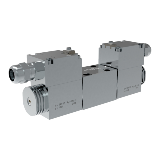
PROPORTIONAL SOLENOID OPERATED
HYDRAULIC DIRECTIONAL CONTROL VALVE
DESIGNED FOR USE IN POTENTIALLY EXPLOSIVE ATMOSPHERES
PRMX2-06
Important!
Read the instructions before using the product.
Save the instructions for future reference.
If the operating instructions are lost, new ones can be found on the ARGO-HYTOS website
The following is the authorised translation of original operating instruction PRMX2-06_15183_2cz_07/2024
issued by the producer:
ARGO-HYTOS s.r.o.
Dělnická 1306, CZ 543 01 VRCHLABÍ
Info.cz@argo-hytos.com
www.argo-hytos.com
Operating instructions_PRMX2-06_15183_2en_07/2024
+ 420 499 403 111
EN
www.argo-hytos.com
Page 1
Advertisement
Chapters
Table of Contents

Related Manuals for Voith ARGO-HYTOS PRMX2-06


Summary of Contents for Voith ARGO-HYTOS PRMX2-06
- Page 1 OPERATING INSTRUCTIONS PROPORTIONAL SOLENOID OPERATED HYDRAULIC DIRECTIONAL CONTROL VALVE DESIGNED FOR USE IN POTENTIALLY EXPLOSIVE ATMOSPHERES PRMX2-06 Important! Read the instructions before using the product. Save the instructions for future reference. www.argo-hytos.com If the operating instructions are lost, new ones can be found on the ARGO-HYTOS website The following is the authorised translation of original operating instruction PRMX2-06_15183_2cz_07/2024 issued by the producer: ARGO-HYTOS s.r.o.
- Page 2 Page 2 www.argo-hytos.com Operating instructions_PRMX2-06_15183_2en_07/2024...
- Page 3 Page 3 www.argo-hytos.com Operating instructions_PRMX2-06_15183_2en_07/2024...
- Page 4 Page 4 www.argo-hytos.com Operating instructions_PRMX2-06_15183_2en_07/2024...
-
Page 5: Table Of Contents
Mandatory traceability Based on legislative requirements, all operators in the logistics chain, from the manufacturer of the certified Ex solenoid coil to the end user of the complete equipement, are obliged to make and maintain traceability records of Ex products, enabling, if necessary, the withdrawal of products of certain serial numbers from the market due to defects of non-conformities, endangering safety of use in an explosive atmosphere. -
Page 6: Overview Of Signal Words And Warning Signs Used In The Text
An overview of signal words and warning signs used in the text Signal word combined with a warning sign used to signify that a dangerous situation which could result in DANGER death or serious injury is imminent. Signal word combined with a warning sign used to signify the occurrence of a potentially dangerous situation WARNING that could result in death or serious injury if not avoided. -
Page 7: Protection Of Electrical Parts
Area of application EQUIPMENT - GROUP I – MINES EQUIPMENT - GROUP II (IIG) - GAS EQUIPMENT - GROUP III (IID) - DUST Category M1– Zone 0 - Zone 20 - IIA (propane) IIIA (combustible particles) Categorie M2 Zone 1 Zone 21 (the device remains IIB (ethylene) -
Page 8: Applicable Legislation And Standards
2.4 Applicable legislation and standards The valve complies with the relevant requirements of legislation and standards: Directive 2014/34/EU (harmonized NV 116/2016) Equipment for potentially explosive atmospheres (ATEX) IECEx OD 009 Operational Document Standards used to assess the conformity of the electrical parts: CENELEC EN IEC 60079-0 Explosive atmospheres –... -
Page 9: Local Certification
2.5 Local certification 2.5.1 Great Britain The product is subject to certification, carried out by entities notified to the EU in accordance with EU legislative regulations and standards, until 31 December 2027. EU certification continues to apply to Northern Ireland.Legislative regulation: Directive 2014/34/EU (ATEX), Regulation 2016: Equipment and Protective Systems Intended for use in Potentially Explosive Atmospheres Applicable standards:... -
Page 10: Risks And Limitations Of Product Use
3. Risks and limitations of product use 3.1 Risks associated with operating in explosive atmospheres Explosive atmosphere type and zone The valve must not be used outside the specified range (see paragraph 1Product use ), in particular it is not DANGER intended for equipment category M1group l (mines) zone 0 group II (gases) and zone 20 group III (dust). -
Page 11: Product Description
4. Product description The hydraulic part of the valve consists of a cast iron body (1) with channel outlets on the lower base, a hardened spool assembly with a control spool inside. The control spool, which is held in its base position by a pair of centering springs, is adjustable from its base position by means of explosi- on-proof certified solenoids (2). -
Page 12: Surface Protection Against Corrosion
4.3 Surface protection against corrosion The valve surface is zinc-coated with 520 h corrosion protection in NSS according to ISO 9227. Surface layer without hexavalent chronium Cr+6. 4.4 Basic technical parameters Parameter Unit Value Nominal valve size DN 06 Maximum pressure in ports P, A, B bar (PSI) 350 (5080) Maximum pressure in port T... -
Page 13: Legislation And Standards
Operating limits: (9.2) Nominal flow rate 10 l/min (2.6 GPM) (7.9) (6.6) Solenoid current: (5.3) 40 % (4.0) 60 % (2.6) 80 % (1.3) 100 % (730) Input pressure p [bar (PSI)] Nominal flow rate 28 l/min (7.4 GPM) (10.6) (10.6) Nominal flow rate 20 l/min (5.3 GPM) (9.2) - Page 14 Spool symbols Type Symbol Type Symbol 2Y51 2Z51 2Y11 2Z11 3Y11 3Z11 6. Target user group All of the above activities related to this valve, in particular installation and connection to the hydraulic circuit, require specialist technical knowledge and experience in the field of hydraulics. The minimum level of competence required is CETOP level 2. This level is generally defined as performing a variety of activities that require an understanding of technical factors and contexts.
-
Page 15: Electrical Connection Of Coils
7.2.1 Electrical connection of coils Coils with DC power supply can be supplied by the manufacturer with the cable attached upon request. If the directional control valve coils do not have a power cable connected, proceed as follows: › A 6 to 8 mm outer diameter cable must be used to connect the coils to the power supply. If using a different type of cable gland, follow the cable gland manufacturer‘s recommendations when selecting the cable diameter. -
Page 16: Connecting The Valve To The Hydraulic Circuit
Electrical wiring diagram of coils Coils with DC power supply and surge protection by bipolar diode = 36 V for U = 12 V DC and 24 V DC Table of coil electrical parameters Coil type with DC Nominal supply Winding resistance Nominal current Limit current Bipolar diode... -
Page 17: Commissioning
Correct installation of the valve The four sealing rings on the base of the body must be undamaged and inserted into the recesses, the WARNING connection surface of the plate sufficiently machined and undamaged, the valve must be fixed with four fastening bolts tightened to the specified torque. -
Page 18: Repairs Carried Out By Specialist
7.5 Exceptional and emergency situations In the event of a power failure to the solenoids or a coil failure, the centering spring will return the valve spool to its base position. Based on the results of the risk analysis, the following potential faults have been identified: ›... -
Page 19: Replacing The Sealing Rings At The Base Of The Valve Body
7.6.1 Replacing a defective valve A defective valve must be removed and replaced with a new one. Repairs to a defective valve may only be carried out by the manufacturer. When replacing the defective valve with a new one, proceed as follows: ›... -
Page 20: Spare Parts Supplied
7.8 Spare parts supplied Ordered as spare parts: see catalog SP 8010 Position Component name Description Ordering number Coil nut Nut sealing O-ring 21.89x2.62 VMQ 70 (silicone) 45904300 Sealing ring actuating system-coil O-ring 22x1.5 VMQ 50 (silicone) Coil nut with manual override N7 Nut sealing O-ring 21.89x2.62 VMQ 70 (silicone) 45904200... - Page 21 GEBRAUCHSANWEISUNG FÜR DAS PRODUKT DER PROPORTIONALE ELEKTROMAGNETISCH BETÄTIGTE HYDRAULISCHE VERTEILER KONZIPIERT FÜR EXPLOSIONSGEFÄHRDETE BEREICHE PRMX2-06 Wichtig! Lesen Sie die Gebrauchsanweisung sorgfältig durch, bevor Sie das Produkt verwenden. Bewahren Sie die Gebrauchsanweisung für späteren Bedarf auf. Beim Verlust der Gebrauchsanweisung erhalten Sie neue Gebrauchsanweisung auf Web-Seiten des Herstellers www.argo-hytos.com ARGO-HYTOS Das Folgende ist die autorisierte Übersetzung der Originalbetriebsanleitung PRMX2-06_15183_2cz_07/2024...
- Page 22 Seite 2 www.argo-hytos.com Gebrauchsanweisung_PRMX2-06_15183_2de_07/2024...
- Page 23 Seite 3 www.argo-hytos.com Gebrauchsanweisung_PRMX2-06_15183_2de_07/2024...
- Page 24 Seite 4 www.argo-hytos.com Gebrauchsanweisung_PRMX2-06_15183_2de_07/2024...
- Page 25 Pflichtige Sicherstellung der Rückverfolgbarkeit Aufgrund der gesetzlichen Bestimmungen sind alle Wirtschaftssubjekte in der Logistikkette, vom Hersteller der zertifizierten Ex-Magnetspu- le bis zum Endverbraucher des kompletten Geräts, verpflichtet, Aufzeichnungen über die Rückverfolgbarkeit von Ex-Produkten zu erstellen und aufzubewahren, die es ermöglichen, Produkte bestimmter Seriennummern aufgrund von Mängeln und Nichtkonformitäten, die die Sicherheit ihrer Verwendung in explosionsgefährdeten Bereichen gefährden, gegebenenfalls vom Markt zu nehmen.
-
Page 26: Liste Der Im Text Verwendeten Signalwörter Und Warnzeichen
Liste der im Text verwendeten Signalwörter und Warnzeichen Ein Signalwort in der Kombination mit einem Warnzeichen, das zum Hinweisen auf eine unmittelbar drohende GEFAHR gefährliche Situation verwendet wird, die zum Tod oder zur schweren Verletzung führen kann. Ein Signalwort in Kombination mit einem Warnzeichen, das zum Hinweisen auf die Entstehung einer potentiell WARNUNG gefährlichen Situation verwendet wird, die zum Tod oder zur schweren Verletzung führen kann, soweit sie nicht verhindert wird. -
Page 27: Ventilschutz Gegen Die Auslösung Der Explosion Einer Explosionsfähigen Atmosphäre
Anwendungsbereiche GERÄTEGRUPPE I - GRUBEN GERÄTEGRUPPE II (IIG) - GASE GERÄTEGRUPPE III (IID) - STAUB Kategorie M1 - NEIN Zone 0 - NEIN Zone 20 - NEIN IIA (Propan) IIIA (brennbare Partikeln) Kategorie M2 Zone 1 Zone 21 (Einrichtung bleibt ausge- IIB (Ethylen) IIIB (nicht leitender Staub) Zone 2... -
Page 28: Verwendete Rechtsvorschriften Und Normen
2.4 Verwendete Rechtsvorschriften und Normen Das Ventil erfüllt die einschlägigen Anforderungen der jeweils geltenden Rechtsvorschriften und Normen: Richtlinie 2014/34/EU (harmonisiert durch die Regierungsverordnung der Tschechischen Republik 116/2016) Anlagen für explosionsgefährdete Bereiche (ATEX) IECEx OD 009 Operational Document Zur Bewertung der Konformität des elektrischen Teils wurden folgende Normen verwendet: CENELEC EN IEC 60079-0 Explosive atmospheres –... -
Page 29: Lokale Zertifizierung
2.5 Lokale Zertifizierung 2.5.1 Großbritannien Das Produkt unterliegt bis zum 31. Dezember 2027 einer Zertifizierung, die von der EU gemäß den EU-Rechtsvorschriften und -Standards gemeldeten Stellen durchgeführt wird. Für Nordirland gilt weiterhin die EU-Zertifizierung. Gesetzliche Regelung: Richtlinie 2014/34/EU (ATEX), Regulation 2016: Equipment and Protective Systems Intended for use in Potentially Explosive Atmospheres Verwendete Standards: 2.5.2 Australien und Neuseeland... -
Page 30: Risiken Und Grenzen Der Produktverwendung
3. Risiken und Grenzen der Produktverwendung 3.1 Risiken im Zusammenhang mit der Funktion in explosionsgefährdeten Bereichen Typ der explosionsfähigen Atmosphäre und die Zone Das Ventil darf nicht außerhalb des spezifizierten Bereichs verwendet werden (siehe Abschnitt 1 Produktverwen- GEFAHR dung), insbesondere ist es nicht für Geräte der Kategorie M1 der Gruppe I (Bergwerke), Zone 0 der Gruppe II (Gase) und Zone 20 der Gruppe III (Staub) bestimmt. -
Page 31: Produktbeschreibung
4. Produktbeschreibung Der hydraulische Teil des Ventils besteht aus einem gusseisernen Gehäuse (1) mit Kanalauslässen an der unteren Basis, einer Baugruppe aus gehärte- tem Stahl schieber mit einem Steuerschieber im Inneren. Der Steuerschieber, der durch ein Paar von Zentrierfedern in der Grundstellung gehalten wird, wird mit Hilfe von Elektromagneten (2), die für explosionsfähige Atmosphären zertifiziert sind, aus der Grundstellung verstellt. -
Page 32: Oberflächenschutz Gegen Korrosion
4.3 Oberflächenschutz gegen Korrosion Die Ventiloberfläche ist verzinkt mit dem Korrosionsschutz 520 h im Salzsprühnebeltest nach ISO 9227 Die Oberflächenschutzschicht enthält kein sechswertiges Chrom Cr+6. 4.4 Grundlegende technische Parameter Parameter Einheit Wert Nenngröße des Ventils DN 06 (D03) Max. Druck in Kanälen P, A, B bar (PSI) 350 (5080) Maximaler Druck im Kanal T... -
Page 33: Verwendete Rechtsvorschriften Und Normen
Leistungskennlinien: (9.2) Nenndurchfluss 10 l/min (2.6 GPM) (7.9) (6.6) Elektromagnetstrom: (5.3) 40 % (4.0) 60 % (2.6) 80 % (1.3) 100 % (730) Eingangsdrck p [bar (PSI)] (10.6) (10.6) Nennvolumenstrom 20 l/min (5,3 GPM) Nennvolumenstrom 28 l/min (7,4 GPM) (9.2) (9.2) (7.9) (7.9) -
Page 34: Benutzerzielgruppe
Tabelle Verbindung der Schieber Symbol Symbol 2Y51 2Z51 2Y11 2Z11 3Y11 3Z11 6. Benutzerzielgruppe Alle angeführten Tätigkeiten im Zusammenhang mit diesem Ventil, insbesondere der Einbau und die Einschaltung in den hydraulischen Kreislauf, erfordern technische Fachkenntnisse und Erfahrungen auf dem Gebiet der Hydraulik. Das erforderliche Mindestmaß an Sachkunde ist Niveau CETOP 2. -
Page 35: Elektrischer Verbindung Der Spulen
7.2.1 Elektrischer Verbindung der Spulen Die Spulen mit der Gleichstromversorgung können vom Hersteller anhand der Bestellung mit dem angeschlossenen Kabel geliefert werden. Wenn die Spulen des Verteilers kein angeschlossenes Speisekabel haben, gehen Sie wie folgt vor: › Für den Anschluss der Spulen an die Stromversorgung muss ein Kabel mit 6 bis 8 mm Außendurchmesser verwendet werden. ›... -
Page 36: Anschluss Des Ventils An Den Hydraulikkreislauf
Elektrischer Schaltplan für Spulen Spulen mit der DC-Stromversorgung und dem Überspannungsschutz durch bipolare Diode = 36 V für U = 12 V DC und 24 V DC Tabelle der elektrischen Parameter der Spulen Wicklungswiderstand Nennstrom Grenzstrom Bipolare Diode Nominale Leistungs- Spulentyp mit der DC- Nennversor- Stromversorgung... -
Page 37: Inbetriebnahme
Korrekter Einbau des Ventils Die vier Dichtungsringe am Boden des Gehäuses müssen unbeschädigt sein und in die Aussparungen eingesetzt werden, die Anschlussfläche der Platte muss ausreichend bearbeitet und unbeschädigt sein, das Ventil muss mit ACHTUNG vier Festigkeitsschrauben befestigt werden, die mit dem vorgeschriebenen Drehmoment angezogen werden. Wenn diese Bedingungen für die richtige Montage des Ventils nicht erfüllt werden, kann es zu einem Austritt der Arbeitsflüssigkeit kommen. -
Page 38: Außerordentliche Situationen Und Notsituationen
7.5 Außerordentliche Situationen und Notsituationen Im Falle des Ausfalls der Stromversorgung der Elektromagneten oder der Störung der Spule bringt die Zentrierfeder den Ventilschieber in seine Grundstellung zurück. Anhand der Ergebnisse der Risikoanalyse wurden folgende potenzielle Mängel festgelegt: › Äußere Undichtheit des Ventils infolge der Beschädigung der Dichtung in der Verbindung mit der Entweichung der Arbeitsflüssigkeit. ›... -
Page 39: Austausch Des Defekten Ventils
7.6.1 Austausch des defekten Ventils Ein defektes Ventil, muss ausgebaut und durch ein neues ersetzt werden. Reparaturen an einem defekten Ventil werden nur vom Hersteller durchgeführt. Beim Austausch des kompletten Ventils und beim Ersetzen des defekten Ventils durch ein neues ist wie folgt vorzugehen: ›... -
Page 40: Gelieferte Ersatzteile
7.8 Gelieferte Ersatzteile Als Ersatzteile können bestellt werden: Siehe Katalog SP 8010 Posten Beschreibung des Ersatzteils Bezeichnung Bestellnummer Spannmutter der Spule Mutter Satz Dichtung unter der Mutter O-Ring 21,89x2,62 VMQ 70 (Silikon) 45904300 Dichtungsring des Kontrollsystem – Spule O-Ring 22x1,5 VMQ 50 (Silikon) Spannmutter mit der Notbetätigung N7 Mutter Satz... -
Page 41: Www.argo-Hytos.com
NÁVOD K POUŽÍTÍ VÝROBKU PROPORCIONÁLNÍ ELEKTROMAGNETICKY OVLÁDANÝ HYDRAULICKÝ ROZVÁDĚČ URČENÝ PRO PROSTŘEDÍ S NEBEZPEČÍM VÝBUCHU PRMX2-06 Důležité! Před použitím výrobku si pozorně přečtěte návod. Návod k použití uchovejte pro budoucí potřebu. www.argo-hytos.com Při ztrátě návodu k použití získáte nový na webových stánkách výrobce ARGO-HYTOS Toto je originální... - Page 42 Strana 2 www.argo-hytos.com Návod k použití_PRMX2-06_15183_2cz_07/2024...
- Page 43 Strana 3 www.argo-hytos.com Návod k použití_PRMX2-06_15183_2cz_07/2024...
- Page 44 Strana 4 www.argo-hytos.com Návod k použití_PRMX2-06_15183_2cz_07/2024...
- Page 45 Povinné zajištění sledovatelnosti Na základě legislativních požadavků jsou všechny hospodářské subjekty v logistickém řetězci, od výrobce certifikované Ex cívky elektromagnetu až po koncového uživatele kompletního zařízení, povinné pořizovat a udržovat záznamy o sledovatelnosti Ex výrobků, umožňující v případě potřeby stažení výrobků určitých výrobních čísel z trhu z důvodu jejich vad a neshod, ohrožujících bezpečnost jejich použití ve výbušné atmosféře.
-
Page 46: Prohlášení O Shodě
Přehled signálních slov a výstražných značek použitých v textu Signální slovo kombinované s výstražnou značkou používané k signalizaci bezprostředně hrozící nebezpečné NEBEZPEČÍ situace, která může mít za následek smrt nebo vážné zranění. Signální slovo kombinované s výstražnou značkou používané k signalizaci vzniku potenciálně nebezpečné VÝSTRAHA situace, která... -
Page 47: Ochrana Ventilu Proti Iniciaci Exploze Výbušné Atmosféry
Oblasti použití: SKUPINA ZAŘÍZENÍ I – DOLY SKUPINA ZAŘÍZENÍ II (IIG) - PLYNY SKUPINA ZAŘÍZENÍ III (IID) - PRACH Kategorie M1 – Zóna 0 - Zóna 20 - IIA (propan) IIIA (hořlavé částice) Kategorie M2 Zóna 1 Zóna 21 IIB (ethylen) IIIB (nevodivý... -
Page 48: Použité Právní Předpisy A Normy
2.4 Použité právní předpisy a normy Ventil splňuje relevantní požadavky právních předpisů a norem v platném znění: Směrnice 2014/34/EU (harmonizované NV ČR 116/2016) Zařízení pro prostředí s nebezpečím výbuchu (ATEX) IECEx OD 009 Operational Document Pro posouzení shody elektrické části byly použity normy: CENELEC EN IEC 60079-0 Explosive atmospheres –... -
Page 49: Lokální Certifikace
2.5 Lokální certifikace 2.5.1 Velká Británie Pro výrobek platí certifikace, provedená EU oznámenými subjekty podle EU legislativních předpisů a norem, až do 31.12.2027. Pro Severní Irsko platí nadále EU certifikace. Legislativní předpis: Směrnice 2014/34/EU (ATEX), Regulation 2016: Equipment and Protective Systems Intended for use in Potentially Explosive Atmospheres Použité... -
Page 50: Rizika A Omezení Použití Výrobku
3. Rizika a omezení použití výrobku 3.1 Rizika spojená s funkcí ve výbušném prostředí Typ výbušné atmosféry a zóna Ventil nesmí být použit mimo stanovený rozsah (viz odstavec 1 Použití výrobku), zejména není určen pro NEBEZPEČÍ kategorii zařízení M1 skupiny I (doly), zónu 0 skupiny II (plyny) a zónu 20 skupiny III (prach). Hrozí iniciace exploze. -
Page 51: Popis Výrobku
4. Popis výrobku Hydraulická část ventilu se skládá z litinového tělesa (1) s výstupy kanálů na spodní základně, sestavy ocelového kaleného šoupátka s řídicím šoupátkem uvnitř. Řídicí šoupátko, které je drženo v základní poloze dvojicí středicích pružin, je přestavováno ze základní polohy pomocí elektromag- netů... -
Page 52: Povrchová Ochrana Proti Korozi
4.3 Povrchová ochrana proti korozi Povrch ventilu je zinkován s ochranou proti korozi 520 h v NSS podle ISO 9227. Vrstva povrchové ochrany neobsahuje šestimocný chróm Cr+6. 4.4 Základní technické parametry Parametr Jednotka Hodnota Jmenovitá světlost ventilu DN 06 (D03) Maximální... -
Page 53: Použité Předpisy A Normy
Výkonové charakteristiky: (9.2) Jmenovitý průtok 10 l/min (2.6 GPM) (7.9) (6.6) Proud elektromagnetu: (5.3) 40 % (4.0) 60 % (2.6) 80 % (1.3) 100 % (730) Vstupní tlak p [bar (PSI)] (10.6) (10.6) Jmenovitý průtok 20 l/min (5.3 GPM) Jmenovitý průtok 28 l/min (7.4 GPM) (9.2) (9.2) (7.9) -
Page 54: Cílová Skupina Uživatelů
Tabulka propojení šoupátek Symbol Symbol 2Y51 2Z51 2Y11 2Z11 3Y11 3Z11 6. Cílová skupina uživatelů Veškeré uvedené činnosti, vztahující se k tomuto ventilu, zejména instalace a zapojení do hydraulického obvodu, vyžadují odborné technické znalosti a zkušenosti v oblasti hydrauliky. Minimální požadovanou úrovní odborné způsobilosti je úroveň CETOP 2. Tato úroveň je obecně definována jako provádění... -
Page 55: Elektrické Připojení Cívek
7.2.1 Elektrické připojení cívek Cívky s DC napájením mohou být na základě objednávky dodány výrobcem s připojeným kabelem. Pokud cívky rozváděče nemají připojený kabel napájení postupujte následovně: › Pro připojení cívek ke zdroji musí být použit kabel o vnějším průměru 6 až 8 mm. ›... -
Page 56: Zapojení Ventilu Do Hydraulického Obvodu
Schéma elektrického zapojení cívek Cívky s DC elektrickým napájením a přepěťovou ochranou pomocí bipolární diody = 36 V pro U = 12 V DC a 24 V DC Tabulka elektrických parametrů cívek Odpor vinutí při Jmen. proud Limitní proud Bipolární dioda Jmen. -
Page 57: Uvedení Do Provozu
Správná montáž ventilu Čtyři těsnicí kroužky na základně tělesa musí být nepoškozené a vložené v zahloubeních, připojovací plocha VAROVÁNÍ desky dostatečně opracovaná a nepoškozená, ventil musí být upevněn pomocí čtyř pevnostních šroubů utažených stanoveným momentem. Při nesplnění těchto podmínek správné montáže ventilu může dojít k úniku pracovní... -
Page 58: Mimořádné A Nouzové Situace
7.5 Mimořádné a nouzové situace Při výpadku elektrického napájení elektromagnetů nebo poruše cívky vrátí středící pružiny šoupátko ventilu do základní polohy. Na základě výsledků analýzy rizik byly stanoveny následující potenciální závady: › Vnější netěsnost ventilu v důsledku poškození těsnění spojená s únikem pracovní kapaliny. ›... -
Page 59: Výměna Vadného Ventilu
7.6.1 Výměna vadného ventilu Vadný ventil musí být demontován a nahrazen novým. Opravy vadného ventilu provádí pouze výrobce. Při výměně ventilu a nahrazení vadného ventilu novým postupujte následovně: › Ujistěte se, že po dobu opravy nebude přítomná výbušná atmosféra. (viz také 7.5) ›... -
Page 60: Dodávané Náhradní Díly
7.8 Dodávané náhradní díly Jako náhradní díly lze objednat: viz katalog SP 8010 Položka Popis součásti Označení Objednací číslo Upínací matice cívky Matice Sada Těsnění pod matici O-kroužek 21,89x2,62 VMQ 70 (silikon) 45904300 Těsnicí kroužek OS – cívka O-kroužek 22x1,5 VMQ 50 (silikon) Upínací...
Need help?
Do you have a question about the ARGO-HYTOS PRMX2-06 and is the answer not in the manual?
Questions and answers