Table of Contents
Advertisement
Quick Links
INSTRUCTIONS FOR USE OF THE PRODUCT
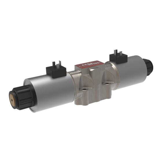
4/2 and 4/3 SPOOL, HYDRAULIC DIRECTIONAL CONTROL VALVE with
BODY AND CONNECTION PATTERN ACCORDING TO ISO 4401
RPE4-10
Important!
Read the instructions before using the product.
Save the instructions for future reference.
If the operating instructions are lost, new ones can be found on the ARGO-HYTOS website
The following is the authorised translation of original operating instruction RPE4-10 no. 14039_1cz_05/2023,
vydaný výrobcem:
ARGO-HYTOS s.r.o.
Dělnická 1306, CZ 543 01 VRCHLABÍ
Info.cz@argo-hytos.com
www.argo-hytos.com
Instructions for use_RPE4-10_14039_1en_05/2023
+ 420 499 403 111
EN
www.argo-hytos.com
Page 1
Advertisement
Table of Contents

Related Manuals for Voith ARGO HYTOS RPE4-10


Summary of Contents for Voith ARGO HYTOS RPE4-10
- Page 1 INSTRUCTIONS FOR USE OF THE PRODUCT 4/2 and 4/3 SPOOL, HYDRAULIC DIRECTIONAL CONTROL VALVE with BODY AND CONNECTION PATTERN ACCORDING TO ISO 4401 RPE4-10 Important! Read the instructions before using the product. Save the instructions for future reference. www.argo-hytos.com If the operating instructions are lost, new ones can be found on the ARGO-HYTOS website The following is the authorised translation of original operating instruction RPE4-10 no.
-
Page 2: Declaration Of Conformity
EU PROHLÁŠENÍ O SHODĚ EU DECLARATION OF CONFORMITY EU-KONFORMITÄTSERKLÄRUNG ARGO-HYTOS s.r.o. Výrobce / Manufacturer / Hersteller: Dělnická 1306 Adresa / Address / Adresse: CZ – 543 15 VRCHLABÍ Česká republika / Czech Republic / Tschechische Republik Identifikační číslo (DIČ)/ Ident. No. / Ident. Nr.: CZ47452498 F12-050.4 Výrobek / Product / Erzeugnis:... -
Page 3: Table Of Contents
Contents of the instructions for use Chapter Page Declaration of Conformity Overview of signal words and warning signs used in the text Overview of symbols and signs used in the text Glossary of technical terms used 1. Product use 2. Product use risks and limitations 3. -
Page 4: Overview Of Signal Words And Warning Signs Used In The Text
An overview of signal words and warning signs used in the text Signal word combined with a warning sign used to signify that a dangerous situation which could result in DANGER death or serious injury is imminent. Signal word combined with a warning sign used to signify a potentially hazardous situation which, if not WARNING avoided, may result in minor or moderate injury. -
Page 5: Product Use Risks And Limitations
2. Product use risks and limitations Maximum operating pressure The valve may be used for a maximum working fluid pressure of 350 bar in the P, A, B channels and 210 bar in DANGER the T channel. Exceeding the maximum pressure can damage the valve and if the compressive strength value of 525 bar in the P, A, B or 315 bar in the T channel is exceeded, the valve will rupture. -
Page 6: Product Description
3. Product description The hydraulic distributor consists of a cast iron body with a DN 10 connection pattern according to ISO 4401 on the base (1). A hardened steel slide moves inside the body, which is held in the basic position by centring springs. The slide is moved to the working position by the power of the control electromagnet (2). -
Page 7: Basic Technical Parameters
3.3 Basic technical parameters Parameter Unit Value Maximum pressure in channels P, A, B bar (PSI) 350 (5080) Maximum pressure in output channel T bar (PSI) 210 (3050) Maximum volumetric flow rate through the valve l/min (GPM) 140 (37) Working fluid temperature range for NBR seal material °C (°F) -30 to +80 (-22 ... -
Page 8: Spool Position Sensor
3.7 Spool Position Sensor Technical parameters Technical Data of the Sensor S1 (NO - switching) / S4 (NC - switching off) Rated power supply voltage V DC Power supply voltage range V DC 10 to 30 Rated current Sensor enclosure protection EN 60529 IP67 Max. -
Page 9: Legal Regulations And Standards
3.8 Legal regulations and standards: The valve meets the relevant requirements of legal regulations and standards as amended: Directive 2006/42/EU On machinery / chapters used: 1.7.4 Instructions for use, Annex I Basic safety requirements ČSN EN ISO 4413:2011 - Hydraulics – General rules and safety requirements for hydraulic systems and their components ČSN EN ISO 13849-1:2017 –... -
Page 10: Coil Electrical Connection Connector Types
CAUTION An E5 connector with a built-in rectifier must be used for AC supply voltage to the coils. Note: The following items must be ordered separately, they are not part of the valve delivery: › High-strength clamping screws M6x45 DIN 912 10.9 (see catalogue SP 8010), possibly bolts for vertical grouping (see catalogue 0020) ›... -
Page 11: Manual Emergency Valve Control
4.3 Manual emergency valve control In the event of a failure of the electromagnet coil or a failure of the coil's electrical supply, the slide can be repositioned, e.g. in order to reach a safe position of the device, using a manual emergency control. However, the valve can only be operated manually up to a pressure of 20-25 bar in the T channel. -
Page 12: Target Group Of Users
5. Target group of users All the activities relate to the valve, especially the installation and adjustment of cracking pressure, require technical expertise and experience in the field of hydraulics. The minimum required level of professional competence is CETOP level 2. This level is generally defined as the performance of various activities that require an understanding of technical factors and contexts. -
Page 13: Coil Connector Positioning
Dimensions in millimeters (inches) Valve with two solenoids RPE4-103*/*E1 Plastic nut 6+1 Nm (4.4+0.7 lbf.ft) RPE4-103*/*E1*S Valve with one solenoid „b“ Valve with one solenoid „a“ Spool symbols X11, C11, H11 Spool symbols R11, R21, A51, P51,Y51, C51, B51, Z51, H51 RPE4-102*/*E1*S Mounting screws 14+1 Nm (10.3+0.7 lbf.ft) -
Page 14: Commissioning
Electromagnet coils (type C 31) The control electromagnet coils are designed for continuous operation (100% ED). The coils have been assessed for compliance with Directive 2014/35/EU (LVD) if the rated voltage is higher than 50 V AC or 75 V DC, Directive 2014/30/EU (EMC) and Directive 2011/65/EU + 2015/863 /EU (RoHS). -
Page 15: Repairs Carried Out By Skilled Persons
Switching off the pressure source and relieving the circuit In the event of an emergency, switch the power source off (pump) and relieve all parts of the hydraulic circuit, CAUTION including the hydraulic accumulators, by connecting them to the tank. Before any work on the circuit, such as removing a valve ensure that the circuit is depressurized. -
Page 16: Product Maintenance
6.7 Product Maintenance 6.7.1 Ongoing checks The valve does not require maintenance during normal operation. At appropriate intervals depending on the environment and operating conditions, we recommend to check on the ongoing basis: › external tightness › electrical wiring and connectors are not damaged ›... -
Page 17: Product Disposal
6.9 Product disposal Remove the valve from the hydraulic circuit (see chapter 6.6 Repairs carried out by skilled persons). Remove as much residual working fluid from the valve as possible. Dispose of the valve in an environmentally friendly manner in accordance with the applicable regulations. The valve is mainly made of recyclable materials (see chapter 3.1 Materials used).
Need help?
Do you have a question about the ARGO HYTOS RPE4-10 and is the answer not in the manual?
Questions and answers