Table of Contents
Advertisement
Available languages
Available languages
Quick Links
Operating instructions
2/2, 3/2 SOLENOID OPERATED,
HYDRAULIC SCREW-IN POPPET-TYPE VALVE, PILOTED
DESIGNED FOR USE IN EXPLOSIVE ATMOSPHERES
SD1EX-A2, SD1EX-A3
SD1EX-A2
2
1
2
1
Important!
Read the instructions before using the product.
Save the instructions for future reference.
If the operating instructions are lost, new ones can be found on the ARGO-HYTOS website
The following is the authorised translation of original operating instruction SD1EX-A2(A3) No.14088_3cz_03/2024,
issued by the manufacturer:
ARGO-HYTOS s.r.o.
Dělnická 1306, CZ 543 01 VRCHLABÍ
Info.cz@argo-hytos.com
www.argo-hytos.com
Operating instructions_SD1EX-A2(A3)_14088_3en_03/2024
SD1EX-A3
+ 420 499 403 111
2
3
1
www.argo-hytos.com
EN
Page 1
Advertisement
Chapters
Table of Contents

Related Manuals for Voith ARGO HYTOS SD1EX-A2


Summary of Contents for Voith ARGO HYTOS SD1EX-A2
- Page 1 Operating instructions 2/2, 3/2 SOLENOID OPERATED, HYDRAULIC SCREW-IN POPPET-TYPE VALVE, PILOTED DESIGNED FOR USE IN EXPLOSIVE ATMOSPHERES SD1EX-A2, SD1EX-A3 SD1EX-A2 SD1EX-A3 Important! Read the instructions before using the product. Save the instructions for future reference. www.argo-hytos.com If the operating instructions are lost, new ones can be found on the ARGO-HYTOS website The following is the authorised translation of original operating instruction SD1EX-A2(A3) No.14088_3cz_03/2024, issued by the manufacturer: ARGO-HYTOS s.r.o.
-
Page 2: Declaration Of Conformity
Declaration of conformity Page 2 www.argo-hytos.com Operating instructions_SD1EX-A2(A3)_14088_3en_03/2024... - Page 3 Page 3 www.argo-hytos.com Operating instructions_SD1EX-A2(A3)_14088_3en_03/2024...
- Page 4 Page 4 www.argo-hytos.com Operating instructions_SD1EX-A2(A3)_14088_3en_03/2024...
-
Page 5: Table Of Contents
Mandatory traceability Based on legislative requirements, all operators in the logistics chain, from the manufacturer of the certified Ex solenoid coil to the end user of the complete equipement, are obliged to make and maintain traceability records of Ex products, enabling, if necessary, the withdrawal of products of certain serial numbers from the market due to defects of non-conformities, endangering safety of use in an explosive atmosphere. -
Page 6: Overview Of Signal Words And Warning Signs Used In The Text
An overview of signal words and warning signs used in the text Signal word combined with a warning sign used to signify that a dangerous situation which could result in DANGER death or serious injury is imminent. Signal word combined with a warning sign used to signify the occurrence of a potentially dangerous situation WARNING that could result in death or serious injury if not avoided. -
Page 7: Protection Of Electrical Parts
The valves are offered in three surface temperature classes: with maximum surface temperature of 135 °C with maximum surface temperature of 100 °C with maximum surface temperature of 85 °C The use of the valve in a given temperature class is conditional on not exceeding the maximum supply voltage of the coil, not exceeding the temperature of the working fluid and the ambient temperature. -
Page 8: Applicable Legislation And Standards
2.4 Applicable legislation and standards The valve complies with the relevant requirements of legislation and standards: Directive 2014/34/EU (harmonized NV 116/2016) Equipment for potentially explosive atmospheres (ATEX) IECEx OD 009 Operational Document The following standards were used to assess the conformity of the electrical part: CENELEC EN IEC 60079-0 Explosive atmospheres –... -
Page 9: Risks And Limitations Of Product Use
Risks and limitations of product use 3.1 Risks associated with operating in explosive atmospheres Explosive atmosphere type and zone The valve must not be used outside the specified range (see paragraph 1Product use ), in particular it is not DANGER intended for equipment category M1group l (mines) zone 0 group II (gases) and zone 20 group III (dust). -
Page 10: Product Description
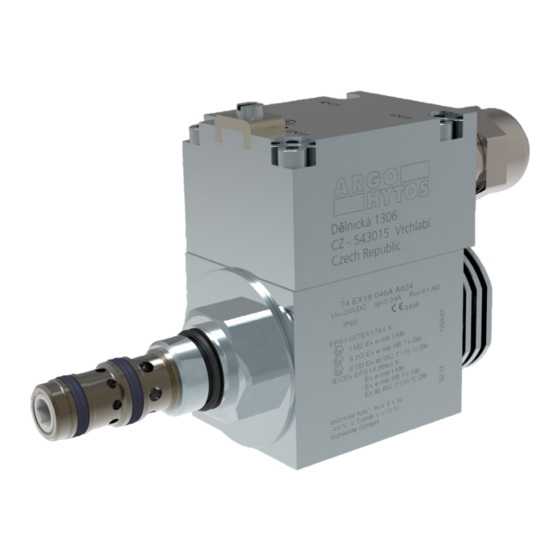
Product description The hydraulic part of the valve consists of a steel housing (A) with radial inlets of port 2 (and port 3 for three way valve) and axial outlets of port 1. A hardened poppet moves inside the seat and is held in its basic position by a return spring. The poppet is repositioned by fluid pressure after opening/closing the control stage, operated by an explosion-proof certified solenoid (B). -
Page 11: Materials Used
4.2 Materials used: Valve bush - steel Poppet - hardened steel Compression spring – patented steel wire for the production of springs Valve seal – NBR, Polyurethane Pole piece, tube, and armature of actuating system, coil housing, terminal box lid and coil fixing nut - low carbon steel Non-magnetic ring and control pin - Cr-Ni stainless steel (8% to 10% Ni) End plug of actuating system –... -
Page 12: Working Fluid
4.5 Working fluid The valve is designed for common hydraulic working fluids: › mineral oils of performance classes HM and HV according to ISO 6734-4 › non-flammable and difficult to ignite hydraulic fluids according to ISO 12922 › environmentally acceptable hydraulic fluids according to ISO 15380 NOTICE: NBR and Polyurethane seal material is not suitable for some working fluid groups, such as the HFD group. -
Page 13: Product Modifications
5. Product modification An overview of possible valve modifications is described in the ordering code. Connection of valve, type of manual override and the electrical parameters of the coil cannot be subsequently changed by the user. In the case of a valve with a 10 W coil, the coil surface temperature and the application for the temperature class can be affected by adjusting the ambient temperature (see 4.4 Ambient temperature range for each class). -
Page 14: Transportation And Storage Of The Product
6. Target user group All of the above activities related to this valve, in particular installation and connection to the hydraulic circuit, require specialist technical knowledge and experience in the field of hydraulics. The minimum level of competence required is CETOP level 2. This level is generally defined as performing a variety of activities that require an understanding of technical factors and contexts. - Page 15 › Unscrew the sealing nut (5) of the cable gland with the wrench A/F 24, remove and check the cable gland seal (2) for damage. › Thread the cable through the removed cable gland parts (2, 3, 5) and the cable gland in the terminal lid (1).
-
Page 16: Connecting The Valve To The Hydraulic Circuit
Table of coil electrical parameters Coil type with DC Nominal supply Winding resistance Nominal current Limit current Bipolar diode Nominal input electric power supply voltage at t = 20 °C power [V DC] [Ω] EX18 046 10W 12V DC 16.1 0.750 0.65 EX18 046 10W 24V DC... - Page 17 Note: Associated tools for production of ports can be ordered from the valve manufacturer (SMT catalogue 0019). Drawings of the ports are also available in the same catalogue. Unscrew the coil nut (4) by turning it counterclockwise. Remove the coil seal ring (3) and coil (2) from the actuating system. The valve (1) is mounted in the cavity without the coil to prevent the valve from tightening in the cavity.
-
Page 18: Commissioning
Correct installation of the valve CAUTION A missing or damaged ring after the thread will cause a leak of working fluid. Missing or damaged rings on the valve bush will cause internal volume loss and unreliable valve operation. The solenoid windings heat up during operation. Effective external cooling must be provided to ensure that the maximum winding temperature is not exceeded, by not exceeding the maximum fluid and ambient temperature and by maintaining minimum volume of the connection block. -
Page 19: Extraordinary And Emergency Situations
7.5 Extraordinary and emergency situations In the event of a power failure to the solenoids or a coil failure, the centering spring will return the valve poppet to the base position. Based on the results of the risk analysis, the following potential faults have been identified: ›... -
Page 20: Product Maintenance
7.6.2 Replacing the sealing rings on the valve housing A sealing ring in the recess behind the thread ensures the valve is sealed in the block and prevents working fluid from leaking out of the block. Sealing rings on the steel valve bush separate the individual ports in the cavity from each other. If the ring is not fitted or is damaged, unwanted interconnection of the ports and unreliable control function of the valve will occur. -
Page 21: Product Disposal
The storage conditions for seals are specified in ISO 2230 - Rubber products - Storage guidelines: Seals to be stored: › in covered, dry and tempered areas at temperatures of +15 to +25 °C, away from direct heat sources › protected from the weather, direct sunlight and ultraviolet radiation ›... - Page 22 GEBRAUCHSANWEISUNG FÜR DAS PRODUKT ELEKTROMAGNETISCH BETÄTIGTE HYDRAULISCHE 2/2-, 3/2-EINBAU-SITZVENTILE; DIREKT GESTEUERT, KONZIPIERT FÜR EXPLOSIONSGEFÄHRDETE BEREICHE SD1EX-A2, SD1EX-A3 SD1EX-A2 SD1EX-A3 Wichtig! Lesen Sie die Gebrauchsanweisung sorgfältig durch, bevor Sie das Produkt verwenden. Bewahren Sie die Gebrauchsanweisung für späteren Bedarf auf. Beim Verlust der Gebrauchsanweisung erhalten Sie neue Gebrauchsanweisung auf Web-Seiten des Herstellers www.argo-hytos.com ARGO-HYTOS Das Folgende ist die autorisierte Übersetzung der Originalbetriebsanleitung SD1EX-A2(A3 )
- Page 23 Konformitätserklärung Seite 2 www.argo-hytos.com Gebrauchsanweisung_SD1EX-A2(A3)_14088_3de_05/2024...
- Page 24 Seite 3 www.argo-hytos.com Gebrauchsanweisung_SD1EX-A2(A3)_14088_2de_12/2023...
- Page 25 Seite 4 www.argo-hytos.com Gebrauchsanweisung_SD1EX-A2(A3)_14088_3de_05/2024...
- Page 26 Pflichtige Sicherstellung der Rückverfolgbarkeit Aufgrund der gesetzlichen Bestimmungen sind alle Wirtschaftssubjekte in der Logistikkette, vom Hersteller der zertifizierten Ex-Magnetspu- le bis zum Endverbraucher des kompletten Geräts, verpflichtet, Aufzeichnungen über die Rückverfolgbarkeit von Ex-Produkten zu erstellen und aufzubewahren, die es ermöglichen, Produkte bestimmter Seriennummern aufgrund von Mängeln und Nichtkonformitäten, die die Sicherheit ihrer Verwendung in explosionsgefährdeten Bereichen gefährden, gegebenenfalls vom Markt zu nehmen.
-
Page 27: Liste Der Im Text Verwendeten Signalwörter Und Warnzeichen
Liste der im Text verwendeten Signalwörter und Warnzeichen Ein Signalwort in der Kombination mit einem Warnzeichen, das zum Hinweisen auf eine unmittelbar drohende GEFAHR gefährliche Situation verwendet wird, die zum Tod oder zur schweren Verletzung führen kann.. Ein Signalwort in Kombination mit einem Warnzeichen, das zum Hinweisen auf die Entstehung einer potentiell WARNUNG gefährlichen Situation verwendet wird, die zum Tod oder zur schweren Verletzung führen kann, soweit sie nicht verhindert wird. -
Page 28: Ventilschutz Gegen Die Auslösung Der Explosion Einer Explosionsfähigen Atmosphäre
Die Ventile werden in drei Oberflächentemperaturklassen angeboten: mit der maximalen Oberflächentemperatur von 135 °C mit der maximalen Oberflächentemperatur von 100 °C mit der maximalen Oberflächentemperatur von 85 °C Der Einsatz des Ventils in der gegebenen Temperaturklasse ist dadurch bedingt, dass die maximale Versorgungsspannung der Spule, die Temperatur der Arbeitsflüssigkeit und die Umgebungstemperatur nicht überschritten werden. -
Page 29: Eurasische Wirtschaftsunion (Eaeu)
2.4 Rechtsvorschriften und Normen Das Ventil erfüllt die einschlägigen Anforderungen der jeweils geltenden Rechtsvorschriften und Normen: Richtlinie 2014/34/EU (harmonisiert durch die Regierungsverordnung der Tschechischen Republik 116/2016) Anlagen für explosionsgefährdete Bereiche (ATEX) IECEx OD 009 Operational Document Zur Bewertung der Konformität des elektrischen Teils wurden folgende Normen verwendet: CENELEC EN IEC 60079-0 Explosive atmospheres –... -
Page 30: Risiken Und Grenzen Der Produktverwendung
3. Risiken und Grenzen der Produktverwendung 3.1 Risiken im Zusammenhang mit der Funktion in explosionsgefährdeten Bereichen Typ der explosionsfähigen Atmosphäre und die Zone Das Ventil darf nicht außerhalb des spezifizierten Bereichs verwendet werden (siehe Abschnitt 1 Produktver- GEFAHR wendung), insbesondere ist es nicht für Geräte der Kategorie M1 der Gruppe I (Bergwerke), Zone 0 der Gruppe II (Gase) und Zone 20 der Gruppe III (Staub) bestimmt. -
Page 31: Produktbeschreibung
4. Produktbeschreibung Der hydraulische Teil des Ventils besteht aus einem Stahlgehäuse (A) mit radialen Einlässen für Kanal 2 (und 3 bei einem Dreiwegeventil) und einem axialen Einlass für Kanal 1. Im Inneren des Sitzes bewegt sich ein gehärteter Kegel, der durch eine Rückstellfeder in seiner Grundstellung gehalten wird. -
Page 32: Verwendete Materialien
4.2 Verwendete Materialien Ventilgehäuse – Stahl Kegel – gehärteter Stahl Druckfeder – patentierter Stahldraht für die Federherstellung Ventildichtungen – NBR, PU Aufsatz, Rohr und der Anker des Betätigungssystems, Mantel und Deckel der Spule, Befestigungsmutter der Spule – kohlenstoffarmer Stahl Nicht magnetischer Ring und Stift des Betätigungssystems – Cr-Ni-Edelstahl Stöpsel des Betätigungssystems –... -
Page 33: Arbeitsflüssigkeit
4.5 Arbeitsflüssigkeit Das Ventil ist für gängige hydraulische Arbeitsflüssigkeiten bestimmt: › Mineralöle der Leistungsklassen HM und HV nach ISO 6734-4 › nicht brennbare und schwer entflammbare Hydraulikflüssigkeiten nach ISO 12922 › umweltverträgliche Hydraulikflüssigkeiten nach ISO 15380 HINWEIS: Die Dichtungsmaterialien NBR und Polyurethan sind für einige Gruppen der Arbeitsflüssigkeiten, wie z. B. die HFD-Gruppe, nicht geeignet. Im Falle der Unsicherheit empfehlen wir, den Test der gegenseitigen Verträglichkeit des Dichtungsmaterials mit der Arbeitsflüssigkeit durchzuführen. -
Page 34: Produktänderung
5. Produktänderung und Bestellschlüssel Die Übersicht über die möglichen Ventilmodifikationen ist im Bestellschlüssel beschrieben. Der Ventilanschluss, die Art der Notbetätigung und die elektrischen Parameter der Spule können vom Benutzer nicht nachträglich geändert werden. Beim Ventil mit der 10-W-Spule können die Oberflächentemperatur der Spule und die Verwendung für die Temperaturklasse durch die Anpassung der Umgebungstemperatur beeinflusst werden (siehe 4.4 Umgebungstemperaturbereich für einzelne Klassen). -
Page 35: Benutzerzielgruppe
6. Benutzerzielgruppe Alle angeführten Tätigkeiten im Zusammenhang mit diesem Ventil, insbesondere der Einbau und die Einschaltung in den hydraulischen Kreislauf, erfordern technische Fachkenntnisse und Erfahrungen auf dem Gebiet der Hydraulik. Das erforderliche Mindestmaß an Sachkunde ist Niveau CETOP 2. Dieses Niveau wird allgemein als die Durchführung verschiedener Tätigkeiten definiert, die ein Verständnis für technische Faktoren und Zusammenhänge erfordern. - Page 36 › Die Überwurfmutter (5) der Kabeldurchführungstülle mit dem Schlüssel s=24 abschrauben, entfernen und die Dichtung der Durchführungstülle (2) auf Beschädigungen überprüfen. › Fädeln Sie das Kabel durch die demontierten Teile der Durchführungstülle (2, 3, 5) und die Durchführungstülle im Deckel der Klemmleiste (1). ›...
-
Page 37: Anschluss Des Ventils An Den Hydraulikkreislauf
Tabelle der elektrischen Parameter der Spulen Wicklungswiderstand Nennstrom Grenzstrom Bipolare Diode Nominale Spulentyp mit der DC- Nennversorgungs- Stromversorgung spannung bei t = 20 °C Leistungsaufnahme [V DC] [Ω] EX18 046 10W 12V DC 16,1 0,750 0,65 EX18 046 10W 24V DC 61,8 0,390 0,34... - Page 38 Bemerkung: Verbundwerkzeuge für die Herstellung die Formbohrung können beim Hersteller der Ventile bestellt werden (SMT Datenblatt 0019). In demselben Datenblatt sind auch Zeichnungen die Formbohrung enthalten. Schrauben Sie die Mutter der Spule (4) ab, indem Sie sie gegen den Uhrzeigersinn drehen. Entfernen Sie den Dichtungsring der Spule (3) und die Spule (2) aus dem Steuersystem.
-
Page 39: Inbetriebnahme
Korrekter Einbau des Ventils Korrekter Einbau des Ventils Korrekter Einbau des Ventils Ein fehlender oder beschädigter Gewindering führt zu einem Austritt von der Arbeitsflüssigkeit. Fehlende oder Ein fehlender oder beschädigter Gewindering führt zu einem Austritt von der Arbeitsflüssigkeit. Fehlende oder Ein fehlender oder beschädigter Gewindering führt zu einem Austritt von der Arbeitsflüssigkeit. -
Page 40: Außerordentliche Situationen Und Notsituationen
7.5 Außerordentliche Situationen und Notsituationen Im Falle des Ausfalls der Stromversorgung der Elektromagneten oder der Störung der Spule bringt die Feder den Ventilkegel in seine Grundstellung zurück. Anhand der Ergebnisse der Risikoanalyse wurden folgende potenzielle Mängel festgelegt: › Äußere Undichtheit des Ventils infolge der Beschädigung der Dichtung in der Verbindung mit der Entweichung der Arbeitsflüssigkeit. ›... -
Page 41: Wartung Des Produkts
7.6.2 Austausch der Dichtungsringe am Ventilgehäuse Der Dichtungsring im Einstich mit dem Gewinde sorgt für die Dichtung des Ventils im Block und verhindert das Austreten von der Arbeitsflüssigkeit aus dem Block. Der oder die Dichtungsringe am Stahlventilgehäuse trennen die einzelnen Kanäle in der Kammer voneinander ab. Ist der Ring nicht montiert oder ist er beschädigt, kommt es zu einer unerwünschten Verbindung der Kanäle und einer unzuverlässigen Regelfunktion des Ventils. -
Page 42: Tätigkeiten Nach Der Beendigung Der Verwendbarkeit Des Produkts
Lagerbedingungen für Dichtungen sind in ISO 2230 - Gummierzeugnisse – Richtlinien für die Lagerung – festgelegt: Die Dichtungen sollen unter folgenden Bedingungen gelagert werden: › in überdachten, trockenen und temperierten Räumen bei Temperaturen von +15 bis +25 °C, entfernt von direkten Wärmequellen ›... - Page 43 Návod k použítí výrobku 2/2, 3/2 ELEKTROMAGNETICKY OVLÁDANÉ HYDRAULICKÉ VESTAVNÉ SEDLOVÉ VENTILY, PŘÍMO ŘÍZENÉ, URČENÉ PRO PROSTŘEDÍ S NEBEZPEČÍM VÝBUCHU SD1EX-A2, SD1EX-A3 SD1EX-A2 SD1EX-A3 Důležité! Před použitím výrobku si pozorně přečtěte návod. Návod k použití uchovejte pro budoucí potřebu. www.argo-hytos.com Při ztrátě...
- Page 44 Prohlášení o shodě Strana 2 www.argo-hytos.com Návod k použití_SD1EX-A2(A3)_14088_3cz_03/2024...
- Page 45 Strana 3 www.argo-hytos.com Návod k použití_SD1EX-A2(A3)_14088_3cz_03/2024...
- Page 46 Strana 4 www.argo-hytos.com Návod k použití_SD1EX-A2(A3)_14088_3cz_03/2024...
- Page 47 Povinné zajištění sledovatelnosti Na základě legislativních požadavků jsou všechny hospodářské subjekty v logistickém řetězci, od výrobce certifikované Ex cívky elektromagnetu až po koncového uživatele kompletního zařízení, povinné pořizovat a udržovat záznamy o sledovatelnosti Ex výrobků, umožňující v případě potřeby stažení výrobků určitých výrobních čísel z trhu z důvodu jejich vad a neshod, ohrožujících bezpečnost jejich použití ve výbušné atmosféře.
-
Page 48: Prohlášení O Shodě
Přehled signálních slov a výstražných značek použitých v textu Signální slovo kombinované s výstražnou značkou používané k signalizaci bezprostředně hrozící nebezpečné NEBEZPEČÍ situace, která může mít za následek smrt nebo vážné zranění. Signální slovo kombinované s výstražnou značkou používané k signalizaci vzniku potenciálně nebezpečné VÝSTRAHA situace, která... -
Page 49: Ochrana Ventilu Proti Iniciaci Exploze Výbušné Atmosféry
Ventily jsou nabízeny ve třech třídách povrchové teploty: s maximální teplotou povrchu 135 °C s maximální teplotou povrchu 100 °C s maximální teplotou povrchu 85 °C Použití ventilu v dané teplotní třídě je podmíněno nepřekročením maximálního napájecího napětí cívky, nepřekročením teploty pracovní... -
Page 50: Použité Právní Předpisy A Normy
2.4 Použité právní předpisy a normy Ventil splňuje relevantní požadavky právních předpisů a norem v platném znění: Směrnice 2014/34/EU (harmonizované NV ČR 116/2016) Zařízení pro prostředí s nebezpečím výbuchu (ATEX) IECEx OD 009 Operational Document Pro posouzení shody elektrické části byly použity normy: CENELEC EN IEC 60079-0 Explosive atmospheres –... -
Page 51: Rizika A Omezení Použití Výrobku
3. Rizika a omezení použití výrobku 3.1 Rizika spojená s funkcí ve výbušném prostředí Typ výbušné atmosféry a zóna Ventil nesmí být použit mimo stanovený rozsah (viz odstavec 1 Použití výrobku), zejména není určen pro NEBEZPEČÍ kategorii zařízení M1 skupiny I (doly), zónu 0 skupiny II (plyny) a zónu 20 skupiny III (prach). Hrozí... -
Page 52: Popis Výrobku
4. Popis výrobku Hydraulická část ventilu se skládá z ocelového pouzdra (A) s radiálními vstupy kanálu 2 (a 3 u trojcestného ventilu) a axiálním vstupem kanálu 1. Uvnitř sedla se pohybuje kalená kuželka, které je v základní poloze držená vratnou pružinou. Kuželka je přestavována do krajní polohy pomocí elektromagnetu (B) s certifikací... -
Page 53: Použité Materiály
4.2 Použité materiály Pouzdro ventilu – ocel Kuželka – kalená ocel Tlačná pružina – ocelový patentovaný drát pro výrobu pružin Těsnění ventilu – NBR, PU Nástavec, trubka a kotva ovládacího systému, plášť cívky, víko svorkovnice, upevňovací matice cívky – nízkouhlíková ocel Nemagnetický... -
Page 54: Pracovní Kapalina
4.5 Pracovní kapalina Ventil je určen pro obvyklé hydraulické pracovní kapaliny: › minerální oleje výkonových tříd HM a HV podle ISO 6734-4 › nehořlavé a obtížně zápalné hydraulické kapaliny podle ISO 12922 › hydraulické kapaliny akceptovatelné z hlediska životního prostředí podle ISO 15380 UPOZORNĚNÍ: Materiály těsnění... -
Page 55: Modifikace Výrobku
5. Modifikace výrobku a objednací klíč Přehled možných modifikací ventilu popisuje objednací klíč. Propojení ventilu, typ nouzového ovládání a elektrické parametry cívky nemůže uživatel následně měnit. U ventilu s 10 W cívkou může být ovlivněna teplota povrchu cívky a použití pro teplotní třídu úpravou teploty okolí (viz. 4.4 Rozsah teploty okolí pro jednotlivé... -
Page 56: Cílová Skupina Uživatelů
6. Cílová skupina uživatelů Veškeré uvedené činnosti, vztahující se k tomuto ventilu, zejména instalace a zapojení do hydraulického obvodu, vyžadují odborné technické znalosti a zkušenosti v oblasti hydrauliky. Minimální požadovanou úrovní odborné způsobilosti je úroveň CETOP 2. Tato úroveň je obecně definována jako provádění... - Page 57 › Odšroubujte převlečnou matici (5) kabelové průchodky pomocí klíče s=24, vyjměte a zkontrolujte nepoškození těsnění průchodky (2). › Provlékněte kabel demontovanými dílci průchodky (2, 3, 5) a průchodkou ve víku svorkovnice (1). › Odstraňte izolaci koncové části kabelu tak, aby po upevnění kabelu v průchodce izolovaná...
-
Page 58: Zapojení Ventilu Do Hydraulického Obvodu
Tabulka elektrických parametrů cívek Odpor vinutí při Jmen. proud Limitní proud Bipolární dioda Jmen. příkon Typ cívky s DC Jmen. napájecí elektrickým napájením napětí t = 20 °C [V DC] [Ω] EX18 046 10W 12V DC 16,1 0,750 0,65 EX18 046 10W 24V DC 61,8 0,390 0,34... - Page 59 Poznámka: Sdružené nástroje pro výrobu komor lze objednat u výrobce ventilů (katalog SMT 0019) Ve stejném katalogu jsou také výkresy komor. Odšroubujte matici cívky (4) otáčením proti směru hodinových ručiček. Sejměte těsnicí kroužek cívky (3) a cívku (2) z ovládacího systému. Ventil (1) se montuje do komory bez cívky, která...
-
Page 60: Uvedení Do Provozu
Správná montáž ventilu Správná montáž ventilu Správná montáž ventilu VAROVÁNÍ VAROVÁNÍ VAROVÁNÍ Chybějící nebo poškozený kroužek za závitem způsobí únik pracovní kapaliny. Chybějící nebo poškozené Chybějící nebo poškozený kroužek za závitem způsobí únik pracovní kapaliny. Chybějící nebo poškozené Chybějící nebo poškozený kroužek za závitem způsobí únik pracovní kapaliny. Chybějící nebo poškozené kroužky na pouzdru ventilu způsobí... -
Page 61: Mimořádné A Nouzové Situace
7.5 Mimořádné a nouzové situace Při výpadku elektrického napájení elektromagnetů nebo poruše cívky vrátí pružina kuželku ventilu do základní polohy. Na základě výsledků analýzy rizik byly stanoveny následující potenciální závady: › Vnější netěsnost ventilu v důsledku poškození těsnění spojená s únikem pracovní kapaliny. ›... -
Page 62: Výměna Těsnicích Kroužků Na Pouzdru Ventilu
7.6.2 Výměna těsnicích kroužků na pouzdru ventilu Těsnicí kroužek v zápichu za závitem zajišťuje těsnost ventilu v bloku a zabraňuje vytékání pracovní kapaliny z bloku. Těsnicí kroužek (kroužky) na ocelovém pouzdru ventilu vzájemně odděluje jednotlivé kanály v komoře. Pokud není namontován nebo je poškozený, dochází k nežádoucímu propojení... -
Page 63: Činnosti Po Skončení Použitelnosti Výrobku
Podmínky skladování těsnění stanovuje norma ISO 2230 – Pryžové výrobky – Pokyny pro skladování: Těsnění mají být skladována: › v krytých, suchých a temperovaných prostorách při teplotách +15 až +25 °C, mimo přímé zdroje tepla › chráněná před povětrnostními vlivy, před přímým slunečním a ultrafialovým zářením ›...
Need help?
Do you have a question about the ARGO HYTOS SD1EX-A2 and is the answer not in the manual?
Questions and answers