Table of Contents
Advertisement
Available languages
Available languages
Quick Links
Operating instructions
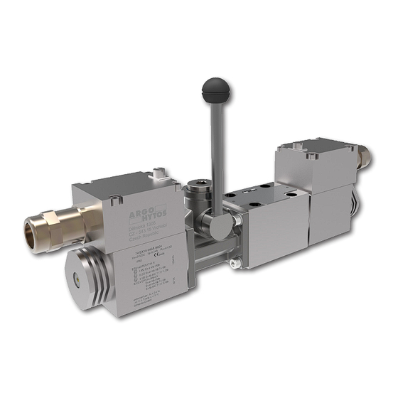
4/3 and 4/2 SOLENOID OPERATED DIRECTIONAL CONTROL VALVE
WITH AUXILIARY LEVER OVERRIDE
DESIGNED FOR USE IN POTENTIALLY EXPLOSIVE ATMOSPHERES
RPERX3-06
Important!
Read the instructions before using the product.
Save the instructions for future reference.
If the operating instructions are lost, new ones can be found on the ARGO-HYTOS website
The following is the authorised translation of original operating instruction RPERX3-06 no 14095_3cz_07/2024
issued by the producer:
ARGO-HYTOS s.r.o.
Dělnická 1306, CZ 543 01 VRCHLABÍ
Info.cz@argo-hytos.com
www.argo-hytos.com
Operating instructions_RPERX3-06_14095_3en_07/2024
+ 420 499 403 111
EN
www.argo-hytos.com
Page 1
Advertisement
Chapters
Table of Contents

Related Manuals for Voith ARGO HYTOS RPERX3-06


Summary of Contents for Voith ARGO HYTOS RPERX3-06
- Page 1 Operating instructions 4/3 and 4/2 SOLENOID OPERATED DIRECTIONAL CONTROL VALVE WITH AUXILIARY LEVER OVERRIDE DESIGNED FOR USE IN POTENTIALLY EXPLOSIVE ATMOSPHERES RPERX3-06 Important! Read the instructions before using the product. Save the instructions for future reference. www.argo-hytos.com If the operating instructions are lost, new ones can be found on the ARGO-HYTOS website The following is the authorised translation of original operating instruction RPERX3-06 no 14095_3cz_07/2024 issued by the producer: ARGO-HYTOS s.r.o.
- Page 2 Page 2 www.argo-hytos.com Operating instructions_RPERX3-06_14095_3en_07/2024...
- Page 3 Page 3 www.argo-hytos.com Operating instructions_RPERX3-06_14095_3en_07/2024...
- Page 4 Page 4 www.argo-hytos.com Operating instructions_RPERX3-06_14095_3en_07/2024...
-
Page 5: Table Of Contents
Mandatory traceability Based on legislative requirements, all operators in the logistics chain, from the manufacturer of the certified Ex solenoid coil to the end user of the complete equipement, are obliged to make and maintain traceability records of Ex products, enabling, if necessary, the withdrawal of products of certain serial numbers from the market due to defects of non-conformities, endangering safety of use in an explosive atmosphere. -
Page 6: Overview Of Signal Words And Warning Signs Used In The Text
An overview of signal words and warning signs used in the text Signal word combined with a warning sign used to signify that a dangerous situation which could result in DANGER death or serious injury is imminent. Signal word combined with a warning sign used to signify the occurrence of a potentially dangerous situation WARNING that could result in death or serious injury if not avoided. -
Page 7: Protection Of Electrical Parts
The valves are available in three surface temperature classes: with a maximum surface temperature of 135 °C with a maximum surface temperature of 100 °C with a maximum surface temperature of 85 °C The use of the valve in the temperature class is subject to the maximum supply voltage of the coil not being exceeded, the working fluid temperature not being exceeded and the ambient temperature not being exceeded (see Table 4.4 Basic technical parameters) 2. -
Page 8: Applicable Legislation And Standards
2.4 Applicable legislation and standards The valve complies with the relevant requirements of legislation and standards: Directive 2014/34/EU (harmonized NV 116/2016) Equipment for potentially explosive atmospheres (ATEX) IECEx OD 009 Operational Document Standards used to assess the conformity of the electrical parts: CENELEC EN IEC 60079-0 Explosive atmospheres –... -
Page 9: Local Certification
2.5 Local certification 2.5.1 Great Britain The product is subject to certification, carried out by entities notified to the EU in accordance with EU legislative regulations and standards, until 31 December 2027. Ireland.Legislative regulation: EU certification continues to apply to Northern Directive 2014/34/EU (ATEX), Regulation 2016: Equipment and Protective Systems Intended for use in Potentially Explosive Atmospheres Applicable standards:... -
Page 10: Risks And Limitations Of Product Use
3. Risks and limitations of product use 3.1 Risks associated with operating in explosive atmospheres Explosive atmosphere type and zone The valve must not be used outside the specified range (see paragraph 1Product use ), in particular it is not DANGER intended for equipment category M1group l (mines) zone 0 group II (gases) and zone 20 group III (dust). -
Page 11: Product Description
4. Product description The hydraulic part of the valve consists of a cast iron body (1) with output ports on the lower base, a hardened steel spool and return springs that hold the spool in its base position. The spool is adjusted to the extreme positions by means of electromagnets (2) certified for explosive atmospheres. The solenoid coils are mounted on the actuation system by means of a special nut (3). -
Page 12: Basic Technical Parameters
4.4 Basic technical parameters Parameter Unit Value Nominal valve size DN 06 Maximum operating pressure at ports P, A, B bar (PSI) 350 (5076) Maximum operating pressure at port T bar (PSI) 100 (1450) Maximum flow volume through the valve l/min (GPM) 60 (15.9) Pressure drop... -
Page 13: Legislation And Standards
4.7 Legislation and standards: ČSN EN ISO 4413 Hydraulics - General rules and safety requirements for hydraulic systems and their components Other regulations and standards used: ČSN ISO 6403 Hydrostatic drives. Valves for flow and pressure control. Test methods ČSN ISO 4411 Measurement of the characteristics Δp = function (Q) of hydraulic valves ČSN EN ISO 9001 Quality management systems... -
Page 14: Target Group Of Users
6. Target group of users All of the above activities related to this valve, in particular installation and connection to the hydraulic circuit, require specialist technical knowledge and experience in the field of hydraulics. The minimum level of competence required is CETOP level 2. This level is generally defined as performing a variety of activities that require an understanding of technical factors and contexts. - Page 15 › Unscrew the cable gland nut (5) of the cable gland with the wrench A/F 24, remove and check the cable gland seal (2) for damage. › Thread the cable through the removed cable gland parts (2, 3, 5) and the cable gland in the terminal lid (1).
-
Page 16: Connecting The Valve To The Hydraulic Circuit
Table of coil electrical parameters Coil type with DC Nominal supply Winding resistance Nominal current Limit current Bipolar diode Input power electric power supply voltage at t = 20 °C [V DC] [Ω] EX18 046 10W 12V DC 16.1 0.750 0.65 EX18 046 10W 24V DC 61.8... -
Page 17: Commissioning
Correct installation of the valve The four sealing rings on the base of the body must be undamaged and inserted into the recesses, the WARNING connection surface of the plate sufficiently machined and undamaged, the valve must be fixed with four fastening bolts tightened to the specified torque. -
Page 18: Repairs Carried Out By Specialist
Shutdown of electrical power, pressure source and circuit relief In the event of an emergency, immediately shut off the electrical power supply to the control solenoids and the pressure source (pump). Relieve all parts of the hydraulic circuit including the hydraulic accumulators by DANGER connecting them to the tank. -
Page 19: Replacing The Sealing Rings At The Base Of The Valve Body
7.6.2 Replacing the sealing rings at the base of the valve body In case of leaks in the dividing plane, the sealing rings must be replaced with new ones. The disassembly and reassembly procedure is similar. › Ensure that no explosive atmosphere is present during the repair (see also 7.5) ›... -
Page 20: Product Disposal
The storage conditions for seals are specified in ISO 2230 - Rubber products - Storage guidelines: Seals to be stored: › in covered, dry and tempered areas at temperatures of +15 to +25 °C, away from direct heat sources › protected from the weather, direct sunlight and ultraviolet radiation ›... - Page 21 GEBRAUCHSANWEISUNG FÜR DAS PRODUKT 4/3- UND 4/2- EXPLOSIONSGESCHÜTZTE WEGEVENTILE MAGNETBETÄTIGT HANDHILFSHEBEL FÜR MAGNETBETÄTIGT VENTILE RPERX3-06 Wichtig! Lesen Sie die Gebrauchsanweisung sorgfältig durch, bevor Sie das Produkt verwenden. Bewahren Sie die Gebrauchsanweisung für späteren Bedarf auf. Beim Verlust der Gebrauchsanweisung erhalten Sie neue Gebrauchsanweisung auf Web-Seiten des Herstellers www.argo-hytos.com ARGO-HYTOS Das Folgende ist die autorisierte Übersetzung der Originalbetriebsanleitung RPERX3-06 Nummer 14095_2cz_07/2024...
- Page 22 Seite 2 www.argo-hytos.com Gebrauchsanweisung_RPERX3-06_14095_2de_07/2024...
- Page 23 Seite 3 www.argo-hytos.com Gebrauchsanweisung_RPERX3-06_14095_2de_07/2024...
- Page 24 Seite 4 www.argo-hytos.com Gebrauchsanweisung_RPERX3-06_14095_2de_07/2024...
- Page 25 Pflichtige Sicherstellung der Rückverfolgbarkeit Aufgrund der gesetzlichen Bestimmungen sind alle Wirtschaftssubjekte in der Logistikkette, vom Hersteller der zertifizierten Ex-Magnetspu- le bis zum Endverbraucher des kompletten Geräts, verpflichtet, Aufzeichnungen über die Rückverfolgbarkeit von Ex-Produkten zu erstellen und aufzubewahren, die es ermöglichen, Produkte bestimmter Seriennummern aufgrund von Mängeln und Nichtkonformitäten, die die Sicherheit ihrer Verwendung in explosionsgefährdeten Bereichen gefährden, gegebenenfalls vom Markt zu nehmen.
- Page 26 Liste der im Text verwendeten Signalwörter und Warnzeichen Ein Signalwort in der Kombination mit einem Warnzeichen, das zum Hinweisen auf eine unmittelbar drohende GEFAHR gefährliche Situation verwendet wird, die zum Tod oder zur schweren Verletzung führen kann.. Ein Signalwort in Kombination mit einem Warnzeichen, das zum Hinweisen auf die Entstehung einer potentiell WARNUNG gefährlichen Situation verwendet wird, die zum Tod oder zur schweren Verletzung führen kann, soweit sie nicht verhindert wird.
-
Page 27: Ventilschutz Gegen Die Auslösung Der Explosion Einer Explosionsfähigen Atmosphäre
Die Ventile werden in drei Oberflächentemperaturklassen angeboten: mit der maximalen Oberflächentemperatur von 135 °C mit der maximalen Oberflächentemperatur von 100 °C mit der maximalen Oberflächentemperatur von 85 °C Der Einsatz des Ventils in der gegebenen Temperaturklasse ist dadurch bedingt, dass die maximale Versorgungsspannung der Spule, die Temperatur der Arbeitsflüssigkeit und die Umgebungstemperatur nicht überschritten werden. -
Page 28: Verwendete Rechtsvorschriften Und Normen
2.4 Verwendete Rechtsvorschriften und Normen Das Ventil erfüllt die einschlägigen Anforderungen der jeweils geltenden Rechtsvorschriften und Normen: Richtlinie 2014/34/EU (harmonisiert durch die Regierungsverordnung der Tschechischen Republik 116/2016) Anlagen für explosionsgefährdete Bereiche (ATEX) IECEx OD 009 Operational Document Zur Bewertung der Konformität des elektrischen Teils wurden folgende Normen verwendet: CENELEC EN IEC 60079-0 Explosive atmospheres –... -
Page 29: Lokale Zertifizierung
2.5 Lokale Zertifizierung 2.5.1 Großbritannien Das Produkt unterliegt bis zum 31. Dezember 2027 einer Zertifizierung, die von der EU gemäß den EU-Rechtsvorschriften und -Standards gemeldeten Stellen durchgeführt wird. Für Nordirland gilt weiterhin die EU-Zertifizierung. Gesetzliche Regelung: Richtlinie 2014/34/EU (ATEX), Regulation 2016: Equipment and Protective Systems Intended for use in Potentially Explosive Atmospheres Verwendete Standards: 2.5.2 Australien und Neuseeland... -
Page 30: Risiken Und Grenzen Der Produktverwendung
3. Risiken und Grenzen der Produktverwendung 3.1 Risiken im Zusammenhang mit der Funktion in explosionsgefährdeten Bereichen Typ der explosionsfähigen Atmosphäre und die Zone Das Ventil darf nicht außerhalb des spezifizierten Bereichs verwendet werden (siehe Abschnitt 1 Produktverwen- GEFAHR dung), insbesondere ist es nicht für Geräte der Kategorie M1 der Gruppe I (Bergwerke), Zone 0 der Gruppe II (Gase) und Zone 20 der Gruppe III (Staub) bestimmt. -
Page 31: Produktbeschreibung
4. Produktbeschreibung Der hydraulische Teil des Ventils besteht aus einem Gusseisengehäuse (1) mit Kanalauslässen am unteren Sockel, einem gehärteten Stahlschieber und Rückstellfedern, die den Schieber in seiner Grundstellung halten. Der Schieber wird mit Hilfe von Elektromagneten (2), mit der Zertifizierung für explo- sionsgefährdete Bereiche, in die Endstellungen verstellt. -
Page 32: Grundlegende Technische Parameter
4.4 Grundlegende technische Parameter Parameter Einheit Wert Nenngröße des Ventils DN 06 (D03) Max. Druck in Kanälen P, A, B bar (PSI) 350 (5080) Maximaler Druck im Kanal T bar (PSI) 210 (3050) Maximaler Volumenstrom durch das Ventil l/min (GPM) 60 (15.9) Druckverluste in der Abhängigkeit vom Durchfluss bar (PSI) -
Page 33: Verwendete Rechtsvorschriften Und Normen
4.7 Verwendete Rechtsvorschriften und Normen: ČSN EN ISO 4413 Hydraulik – Allgemeine Regeln und Sicherheitsanforderungen an hydraulische Systeme und ihre Komponenten ČSN ISO 6403 Hydrostatische Antriebe. Ventile zur Durchfluss- und Druckregelung. Prüfmethoden ČSN ISO 4411 Messung der Kennlinien Δp = Funktion (Q) bei hydraulischen Ventilen ČSN EN ISO 9001 Qualitätsmanagementsysteme ČSN EN ISO 12100... -
Page 34: Benutzerzielgruppe
6. Benutzerzielgruppe Alle angeführten Tätigkeiten im Zusammenhang mit diesem Ventil, insbesondere der Einbau und die Einschaltung in den hydraulischen Kreislauf, erfordern technische Fachkenntnisse und Erfahrungen auf dem Gebiet der Hydraulik. Das erforderliche Mindestmaß an Sachkunde ist Niveau CETOP 2. Dieses Niveau wird allgemein als die Durchführung verschiedener Tätigkeiten definiert, die ein Verständnis für technische Faktoren und Zusammen- hänge erfordern. - Page 35 › Die Überwurfmutter (5) der Kabeldurchführungstülle mit dem Schlüssel s=24 abschrauben, entfernen und die Dichtung der Durchführungstülle (2) auf Beschädigungen überprüfen. › Fädeln Sie das Kabel durch die demontierten Teile der Durchführungstülle (2, 3, 5) und die Durchführungstülle im Deckel der Klemmleiste (1). ›...
-
Page 36: Anschluss Des Ventils An Den Hydraulikkreislauf
Tabelle der elektrischen Parameter der Spulen Wicklungswiderstand Nennstrom Grenzstrom Bipolare Diode Nominale Spulentyp mit der DC- Nennversorgungs- Stromversorgung spannung bei t = 20 °C Leistungsaufnahme [V DC] [Ω] EX18 046 10W 12V DC 16,1 0,750 0,65 EX18 046 10W 24V DC 61,8 0,390 0,34... -
Page 37: Inbetriebnahme
Korrekter Einbau des Ventils Die vier Dichtungsringe am Boden des Gehäuses müssen unbeschädigt sein und in die Aussparungen eingesetzt werden, die Anschlussfläche der Platte muss ausreichend bearbeitet und unbeschädigt sein, das Ventil muss mit ACHTUNG vier Festigkeitsschrauben befestigt werden, die mit dem vorgeschriebenen Drehmoment angezogen werden. Bei der Nichteinhaltung dieser Bedingungen für den ordnungsgemäßen Einbau des Ventils kann es zum zum Austritt der Arbeitsflüssigkeit kommen. -
Page 38: Reparaturen Durch Sachkundige Personen
Abschaltung der Stromversorgung, der Druckquelle und die Entlastung des Kreislaufs Schalten Sie im Notfall sofort die Stromzufuhr zu den Steuermagneten und die Druckquelle (Pumpe) aus. Entlasten Sie alle Teile des Hydraulikkreislaufs, einschließlich der Hydraulikspeicher, indem Sie sie GEFAHR mit dem Tank verbinden. Ein defektes Ventil kann zu einer gefährlichen Betriebssituation führen, weil es die Kontrolle verliert. -
Page 39: Austausch Der Dichtungsringe Auf Der Ausgangsfläche Des Ventilgehäuses
7.6.2 Austausch der Dichtungsringe auf der Ausgangsfläche des Ventilgehäuses Im Falle der Undichtheit in der Trennebene müssen die Dichtungsringe durch neue ersetzt werden. Das Vorgehen für die Demontage und den Wiedereinbau ist ähnlich. › Vergewissern Sie sich, dass während der Reparaturzeit keine explosionsfähige Atmosphäre vorhanden ist (siehe auch 7.5). ›... -
Page 40: Tätigkeiten Nach Der Beendigung Der Verwendbarkeit Des Produkts
Die Lagerbedingungen für Dichtungen sind in ISO 2230 – Gummierzeugnisse – Richtlinien für die Lagerung – festgelegt: Die Dichtungen sollen unter folgenden Bedingungen gelagert werden: › in überdachten, trockenen und temperierten Räumen bei Temperaturen von +15 bis +25 °C, entfernt von direkten Wärmequellen ›... -
Page 41: Www.argo-Hytos.com
NÁVOD K POUŽÍTÍ VÝROBKU 4/3 a 4/2 ELEKTROMAGNETICKY OVLÁDANÝ HYDRAULICKÝ ROZVÁDĚČ S RUČNÍM PÁKOVÝM OVLADAČEM, URČENÝ PRO PROVOZ V PROSTŘEDÍ S NEBEZPEČÍM VÝBUCHU RPERX3-06 Důležité! Před použitím výrobku si pozorně přečtěte návod. Návod k použití uchovejte pro budoucí potřebu. www.argo-hytos.com Při ztrátě... - Page 42 Strana 2 www.argo-hytos.com Návod k použití_RPERX3-06_14095_2cz_07/2024...
- Page 43 Strana 3 www.argo-hytos.com Návod k použití_RPERX3-06_14095_2cz_07/2024...
- Page 44 Strana 4 www.argo-hytos.com Návod k použití_RPERX3-06_14095_2cz_07/2024...
- Page 45 Povinné zajištění sledovatelnosti Na základě legislativních požadavků jsou všechny hospodářské subjekty v logistickém řetězci, od výrobce certifikované Ex cívky elektromag- netu až po koncového uživatele kompletního zařízení, povinné pořizovat a udržovat záznamy o sledovatelnosti Ex výrobků, umožňující v případě potřeby stažení výrobků určitých výrobních čísel z trhu z důvodu jejich vad a neshod, ohrožujících bezpečnost jejich použití ve výbušné...
-
Page 46: Prohlášení O Shodě
Přehled signálních slov a výstražných značek použitých v textu Signální slovo kombinované s výstražnou značkou používané k signalizaci bezprostředně hrozící nebezpečné NEBEZPEČÍ situace, která může mít za následek smrt nebo vážné zranění. Signální slovo kombinované s výstražnou značkou používané k signalizaci vzniku potenciálně nebezpečné VÝSTRAHA situace, která... -
Page 47: Ochrana Ventilu Proti Iniciaci Exploze Výbušné Atmosféry
Ventily jsou nabízeny ve třech třídách povrchové teploty: s maximální teplotou povrchu 135 °C s maximální teplotou povrchu 100 °C s maximální teplotou povrchu 85 °C Použití ventilu v dané teplotní třídě je podmíněno nepřekročením maximálního napájecího napětí cívky, nepřekročením teploty pracovní... -
Page 48: Použité Právní Předpisy A Normy
2.4 Použité právní předpisy a normy Ventil splňuje relevantní požadavky právních předpisů a norem v platném znění: Směrnice 2014/34/EU (harmonizované NV ČR 116/2016) Zařízení pro prostředí s nebezpečím výbuchu (ATEX) IECEx OD 009 Operational Document Pro posouzení shody elektrické části byly použity normy: CENELEC EN IEC 60079-0 Explosive atmospheres –... -
Page 49: Lokální Certifikace
2.5 Lokální certifikace 2.5.1 Velká Británie Pro výrobek platí certifikace, provedená EU oznámenými subjekty podle EU legislativních předpisů a norem, až do 31.12.2027. Pro Severní Irsko platí nadále EU certifikace. Legislativní předpis: Směrnice 2014/34/EU (ATEX), Regulation 2016: Equipment and Protective Systems Intended for use in Potentially Explosive Atmospheres Použité... -
Page 50: Rizika A Omezení Použití Výrobku
3. Rizika a omezení použití výrobku 3.1 Rizika spojená s funkcí ve výbušném prostředí Typ výbušné atmosféry a zóna Ventil nesmí být použit mimo stanovený rozsah (viz odstavec 1 Použití výrobku), zejména není určen pro NEBEZPEČÍ kategorii zařízení M1 skupiny I (doly), zónu 0 skupiny II (plyny) a zónu 20 skupiny III (prach). Hrozí iniciace exploze. -
Page 51: Popis Výrobku
4. Popis výrobku Hydraulická část ventilu se skládá z litinového tělesa (1) s výstupy kanálů na spodní základně, ocelového kaleného šoupátka a vratných pružin, které drží šoupátko v základní poloze. Šoupátko je přestavováno do krajních poloh pomocí elektromagnetů (2) s certifikací pro výbušné prostředí. Cívky elektromagnetů... -
Page 52: Základní Technické Parametry
4.4 Základní technické parametry Parametr Jednotka Hodnota Jmenovitá světlost ventilu DN 06 (D03) Maximální tlak v kanálech P, A, B bar (PSI) 350 (5080) Maximální tlak v kanálu T bar (PSI) 210 (3050) Maximální objemový průtok ventilem l/min (GPM) 60 (15.9) Tlakové... -
Page 53: Použité Předpisy A Normy
4.7 Použité předpisy a normy: ČSN EN ISO 4413 Hydraulika – Všeobecná pravidla a bezpečnostní požadavky na hydraulické systémy a jejich součásti ČSN ISO 6403 Hydrostatické pohony. Ventily pro řízení průtoku a tlaku. Zkušební metody ČSN ISO 4411 Měření charakteristik Δp = funkce (Q) u hydraulických ventilů ČSN EN ISO 9001 Systémy managementu jakosti ČSN EN ISO 12100... -
Page 54: Cílová Skupina Uživatelů
6. Cílová skupina uživatelů Veškeré uvedené činnosti, vztahující se k tomuto ventilu, zejména instalace a zapojení do hydraulického obvodu, vyžadují odborné technické znalosti a zkušenosti v oblasti hydrauliky. Minimální požadovanou úrovní odborné způsobilosti je úroveň CETOP 2. Tato úroveň je obecně definována jako provádění... - Page 55 › Odšroubujte převlečnou matici (5) kabelové průchodky pomocí klíče s=24, vyjměte a zkontrolujte nepoškození těsnění průchodky (2). › Provlékněte kabel demontovanými dílci průchodky (2, 3, 5) a průchodkou ve víku svorkovnice (1). › Odstraňte izolaci koncové části kabelu tak, aby po upevnění kabelu v průchodce izolovaná...
-
Page 56: Zapojení Ventilu Do Hydraulického Obvodu
Tabulka elektrických parametrů cívek Odpor vinutí při Jmen. proud Limitní proud Bipolární dioda Jmen. příkon Typ cívky s DC Jmen. napájecí elektrickým napájením napětí t = 20 °C [V DC] [Ω] EX18 046 10W 12V DC 16,1 0,750 0,65 EX18 046 10W 24V DC 61,8 0,390 0,34... -
Page 57: Uvedení Do Provozu
Správná montáž ventilu Čtyři těsnicí kroužky na základně tělesa musí být nepoškozené a vložené v zahloubeních, připojovací plocha VAROVÁNÍ desky dostatečně opracovaná a nepoškozená, ventil musí být upevněn pomocí čtyř pevnostních šroubů utažených stanoveným momentem. Při nesplnění těchto podmínek správné montáže ventilu může dojít k úniku pracovní... -
Page 58: Opravy, Prováděné Osobami Znalými
Vypnutí elektrického napájení, zdroje tlaku a odlehčení obvodu Při vzniku nouzové situace ihned vypněte zdroj elektrického napájení ovládacích elektromagnetů a zdroj tlaku (čerpadlo). Odlehčete všechny části hydraulického obvodu včetně hydraulických akumulátorů jejich propojením NEBEZPEČÍ s nádrží. Nefunkční ventil může způsobit vznik nebezpečné provozní situace způsobené ztrátou řízení. Poškozená... -
Page 59: Výměna Těsnicích Kroužků Na Základně Tělesa Ventilu
7.6.2 Výměna těsnicích kroužků na základně tělesa ventilu V případě netěsnosti v dělicí rovině je nutné nahradit těsnicí kroužky novými. Postup demontáže a zpětné montáže je obdobný. › Ujistěte se, že po dobu opravy nebude přítomná výbušná atmosféra (viz také 7.5). ›... -
Page 60: Činnosti Po Skončení Použitelnosti Výrobku
Podmínky skladování těsnění stanovuje norma ISO 2230 – Pryžové výrobky – Pokyny pro skladování: Těsnění mají být skladována: › v krytých, suchých a temperovaných prostorách při teplotách +15 až +25 °C, mimo přímé zdroje tepla › chráněná před povětrnostními vlivy, před přímým slunečním a ultrafialovým zářením ›...
Need help?
Do you have a question about the ARGO HYTOS RPERX3-06 and is the answer not in the manual?
Questions and answers